Call Us Today 08 6314 1130

Welcome to Verti Block WA

Diamond Precast Website

Downloads

Information on Verti-block from brochures to detailed drawings and design manuals

Cover of Retaining Wall Design Manual showing a large concrete block and a stone retaining wall under a blue sky, with the VertiBlock logo.

Manual

Construction and deisign drawing measurements

Download
Brochure featuring Verti-Block retaining wall block with benefits listed, a stone retaining wall, and Verti-Block logo.

Brochure

An overview of the Verti Block deisgn / product

Download

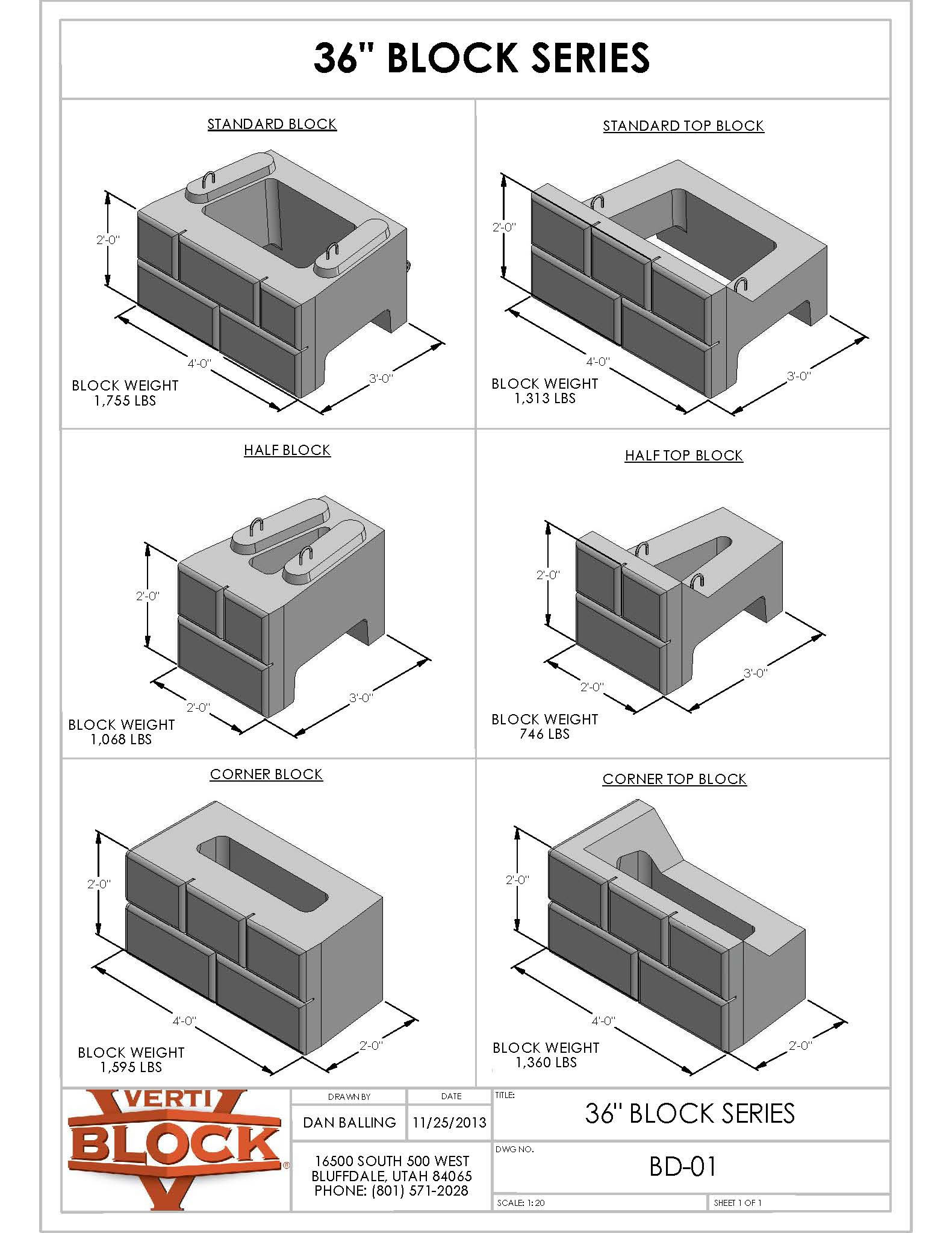
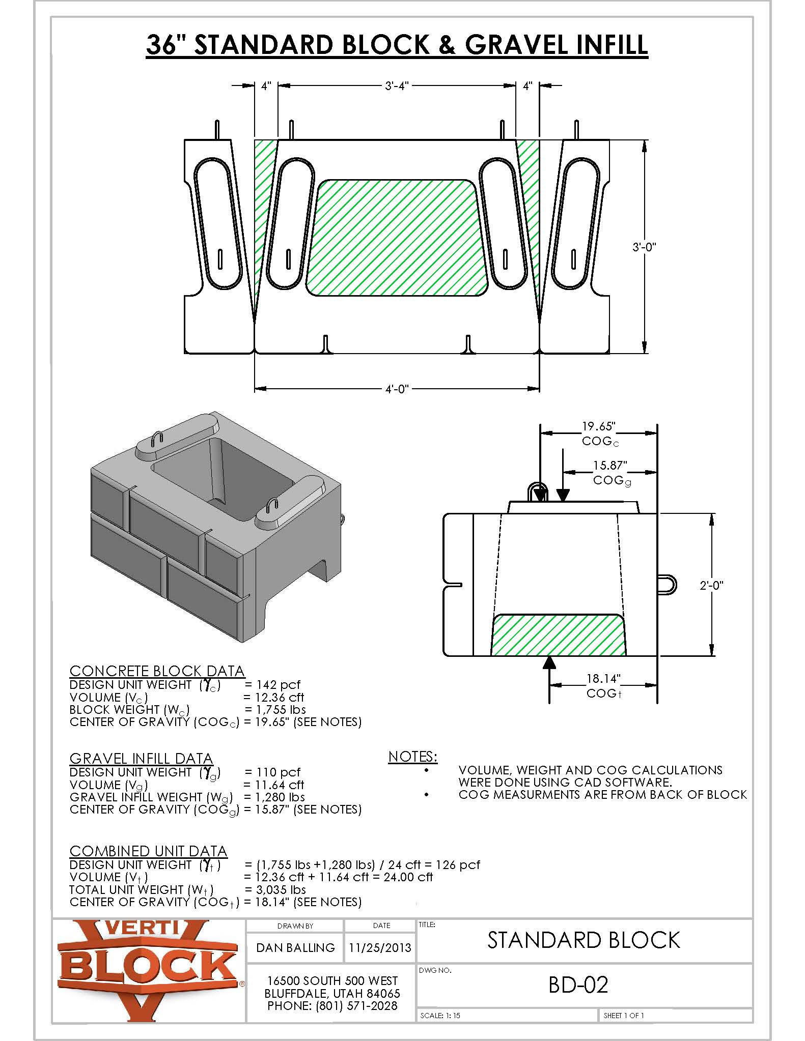
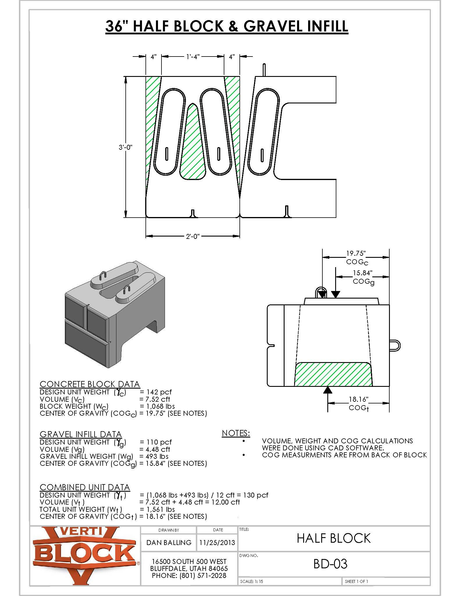
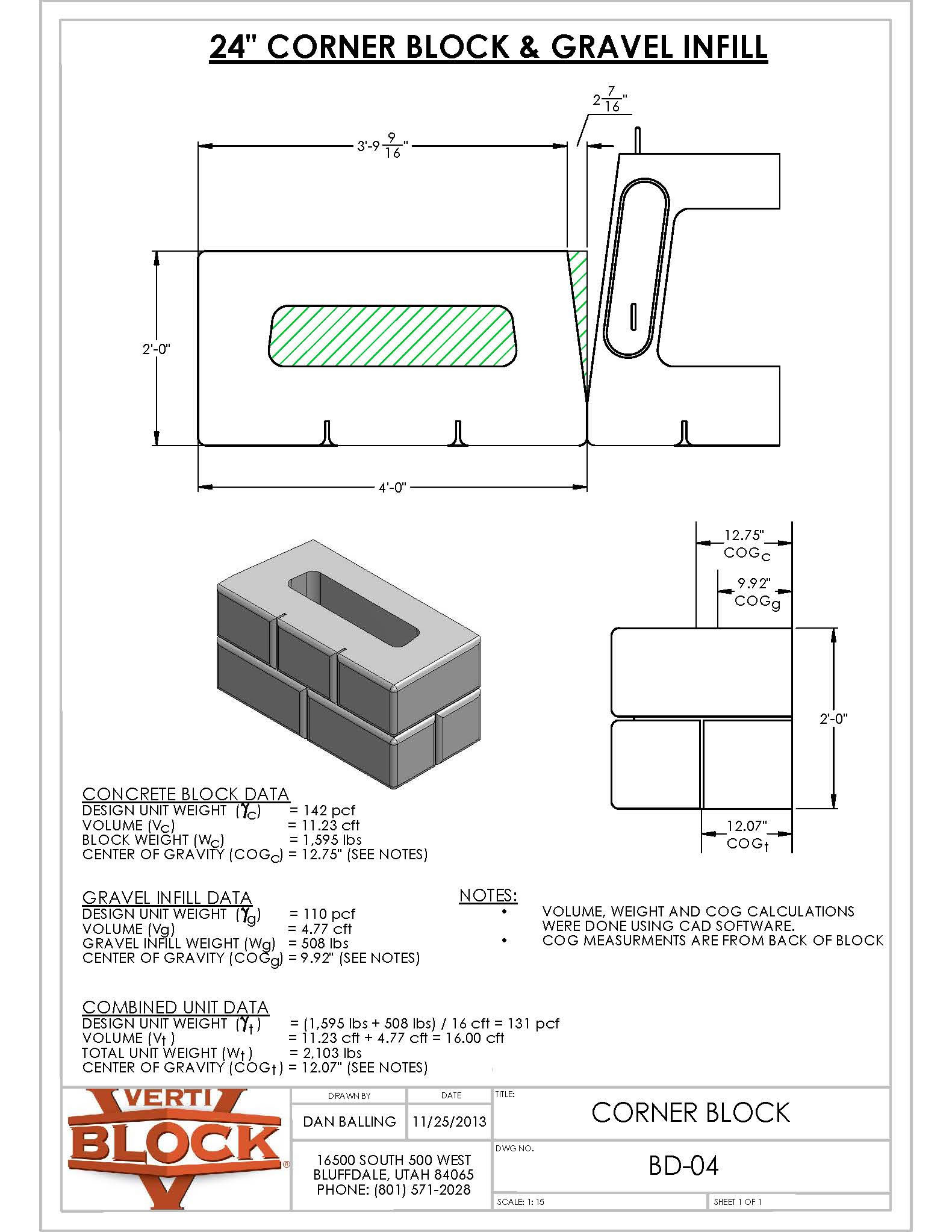
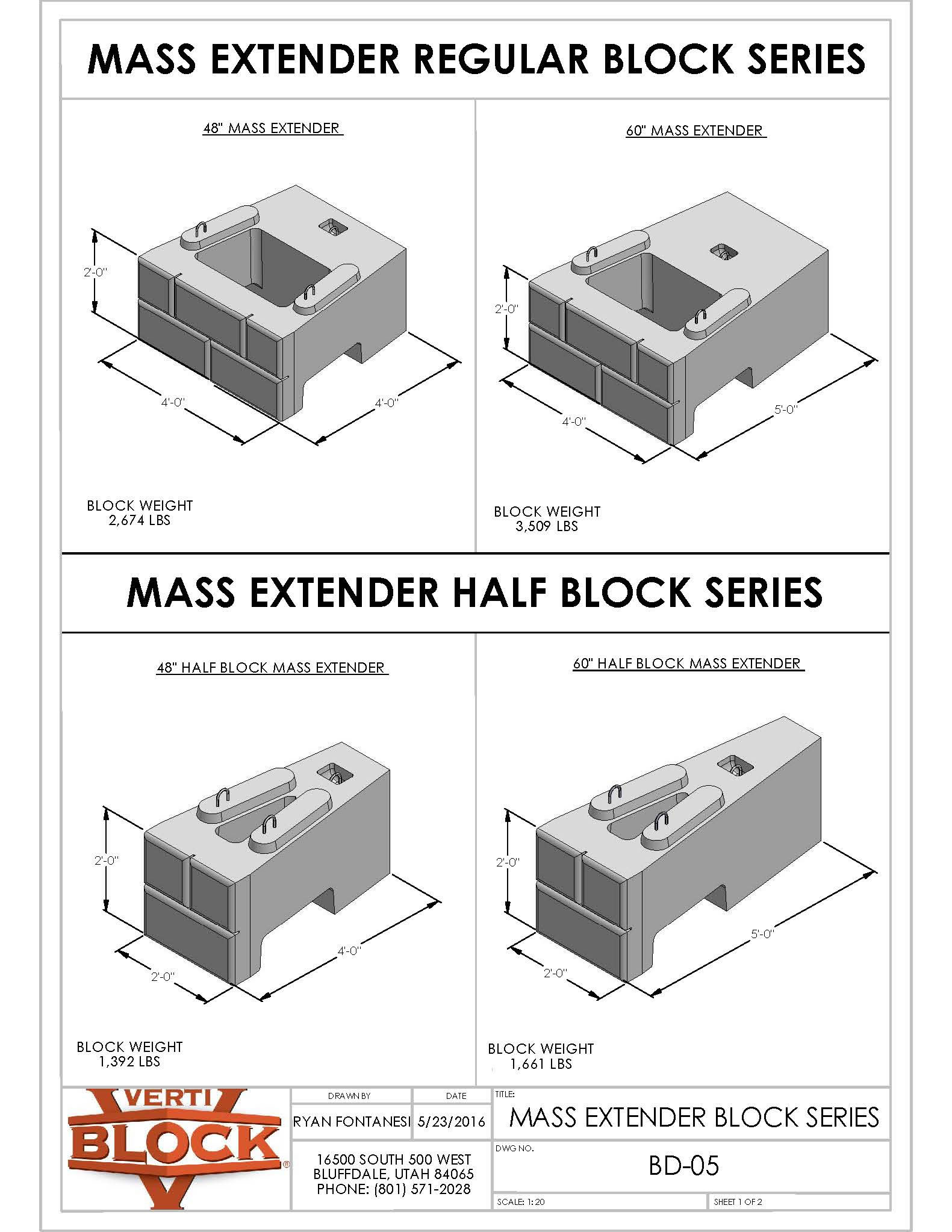
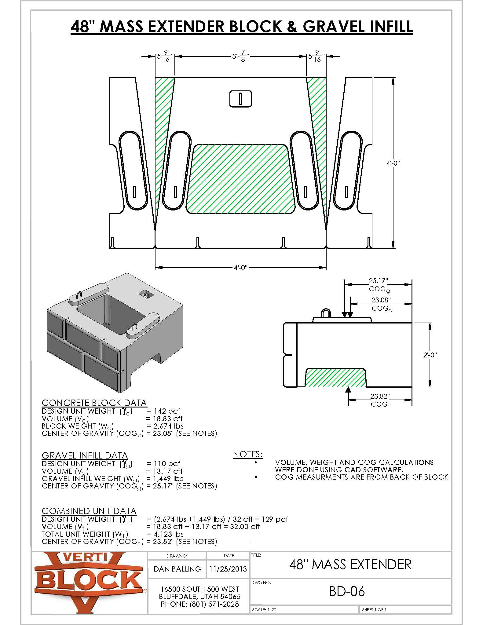
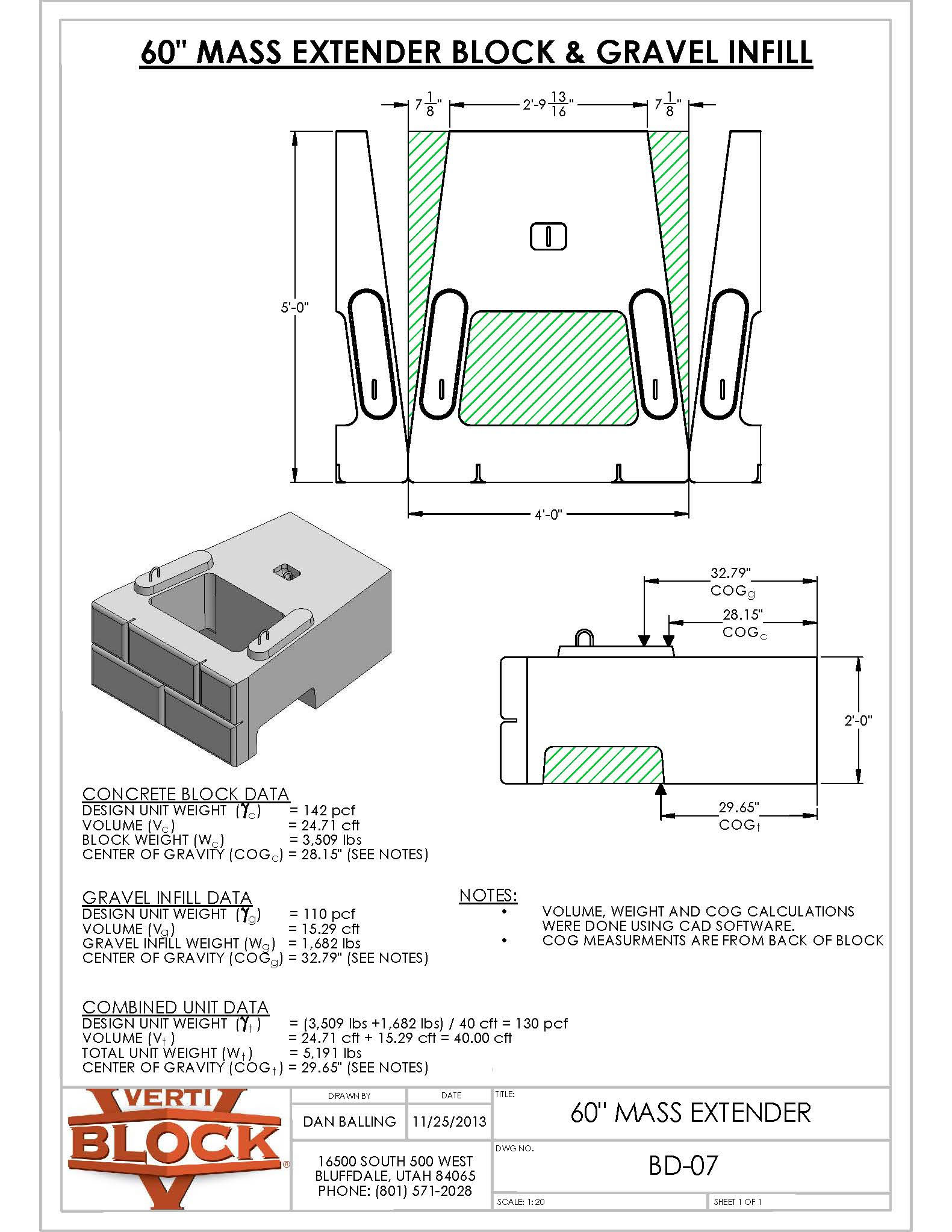
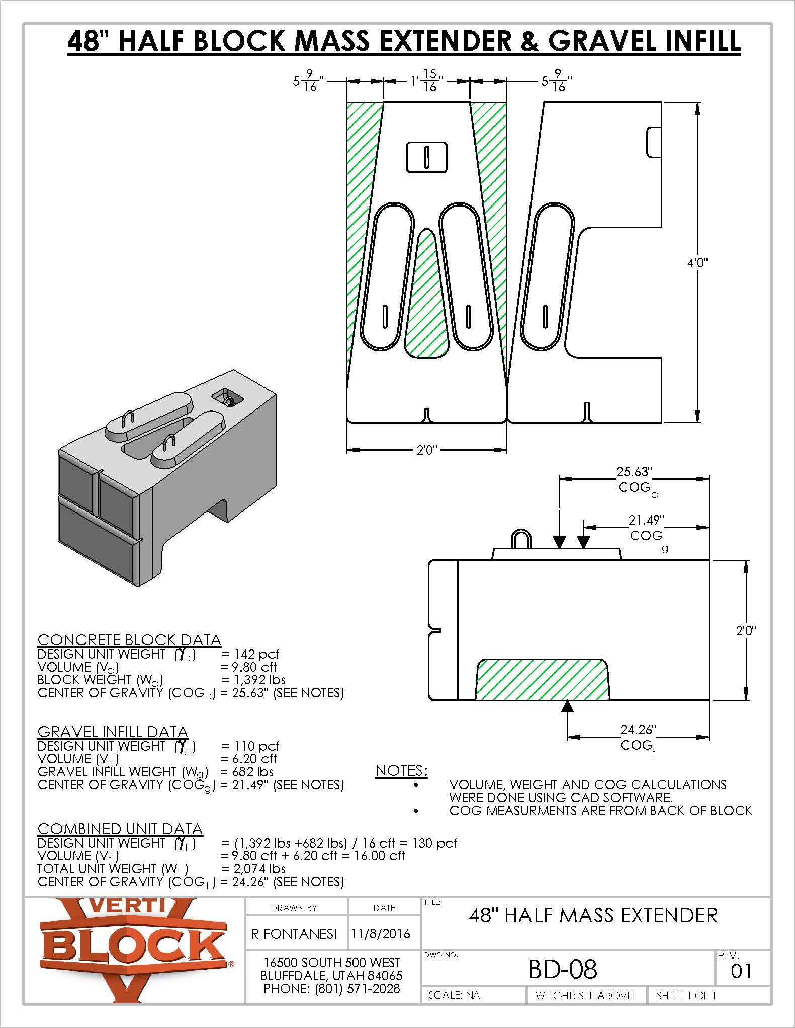
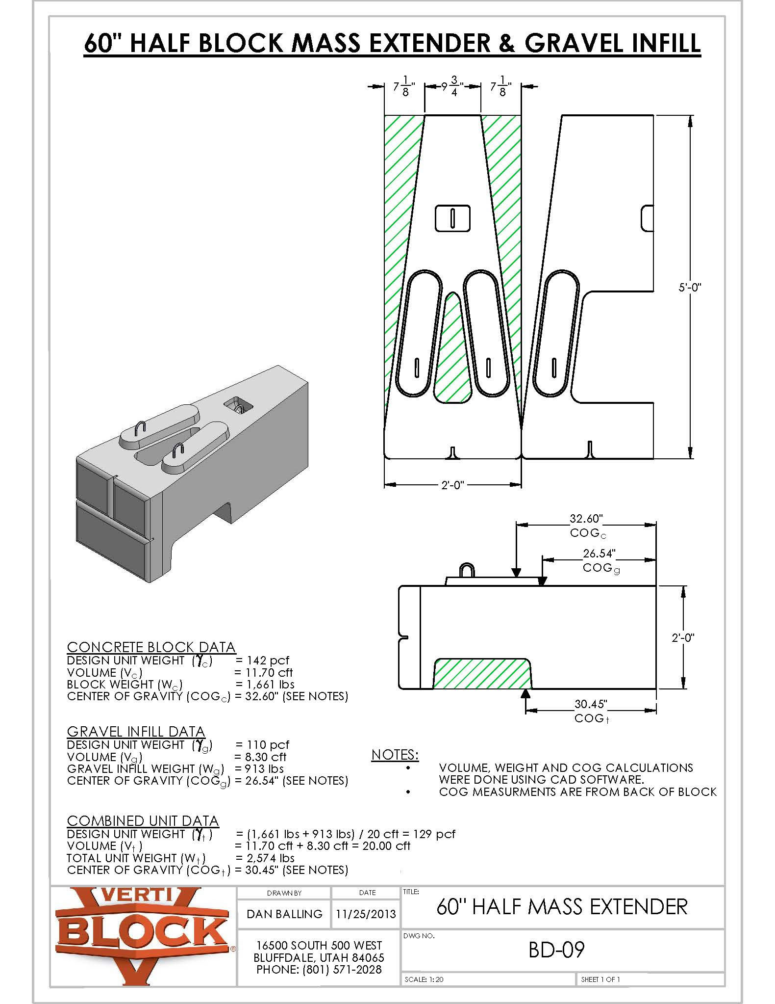
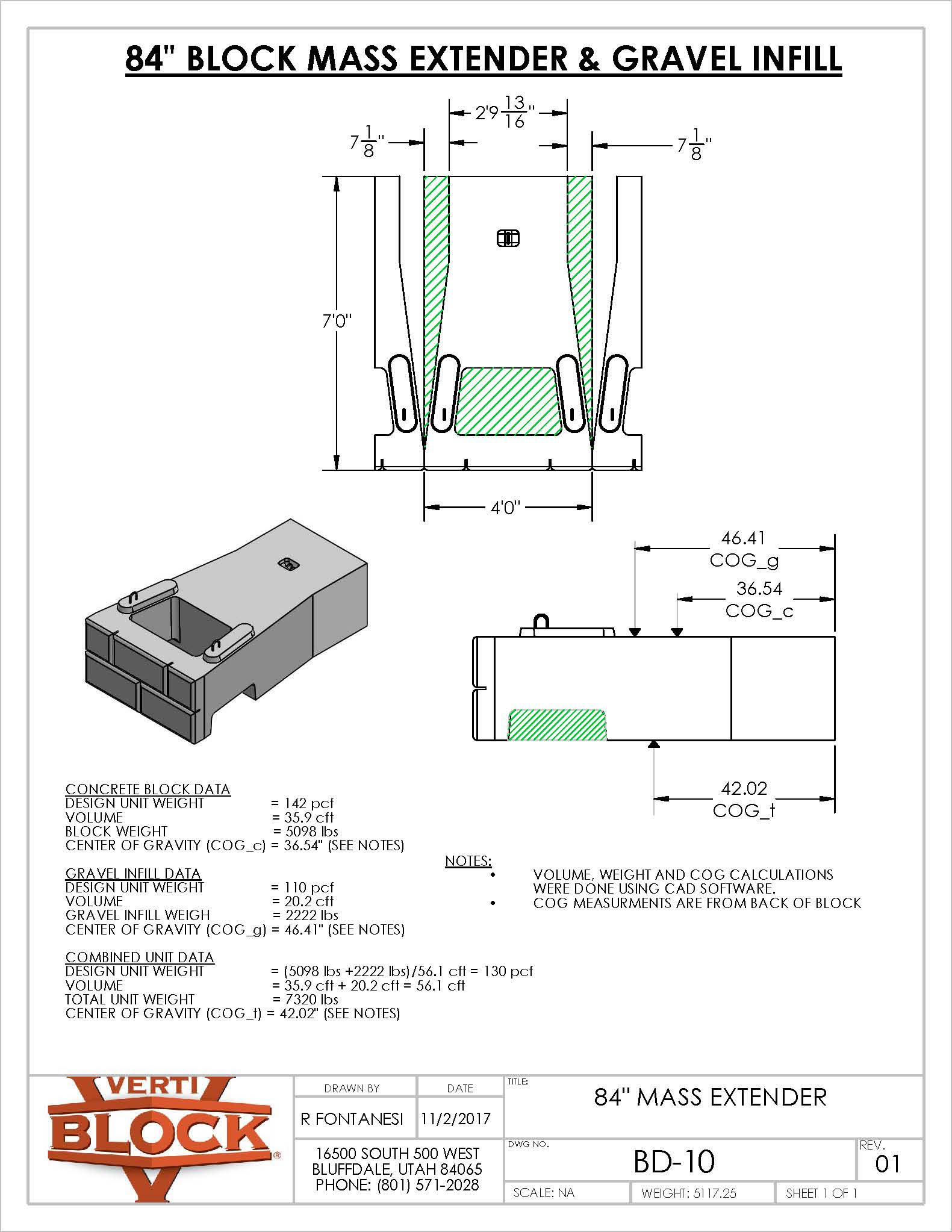
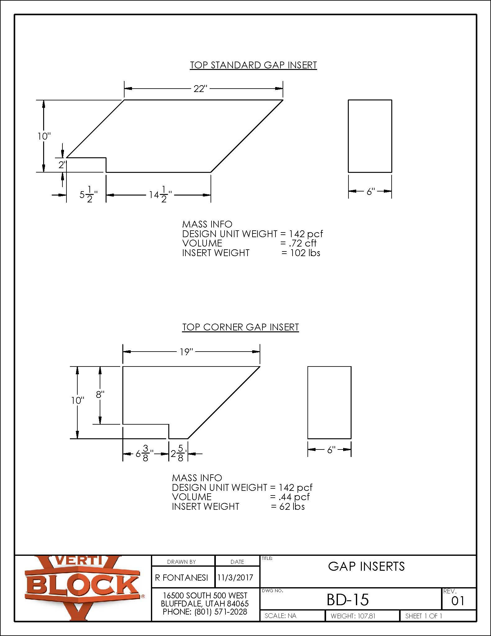
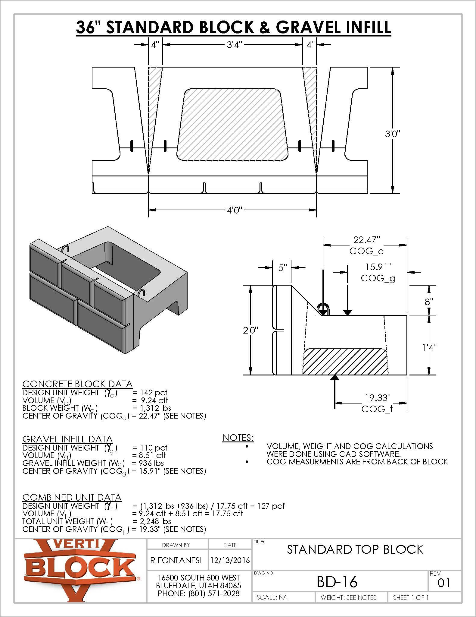
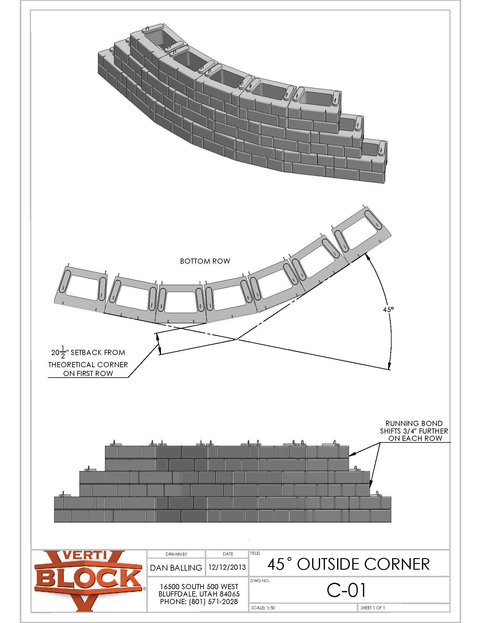
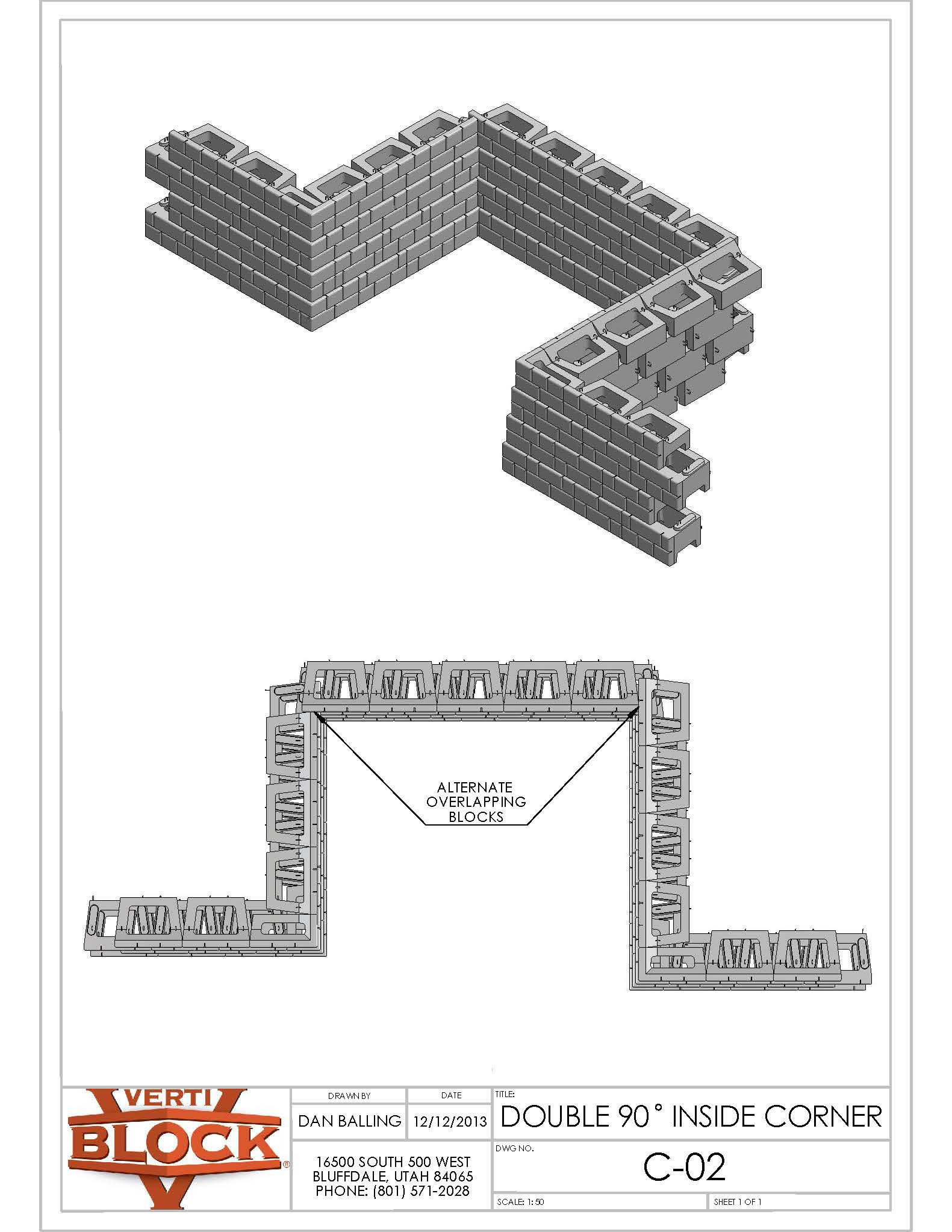
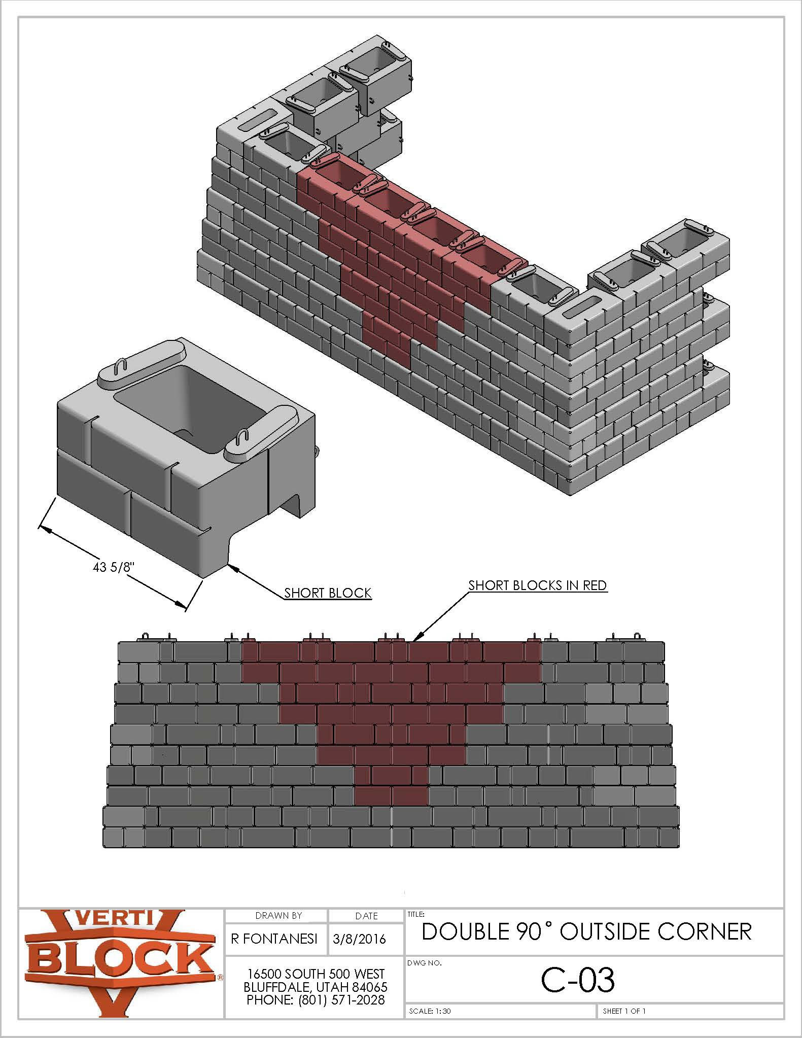
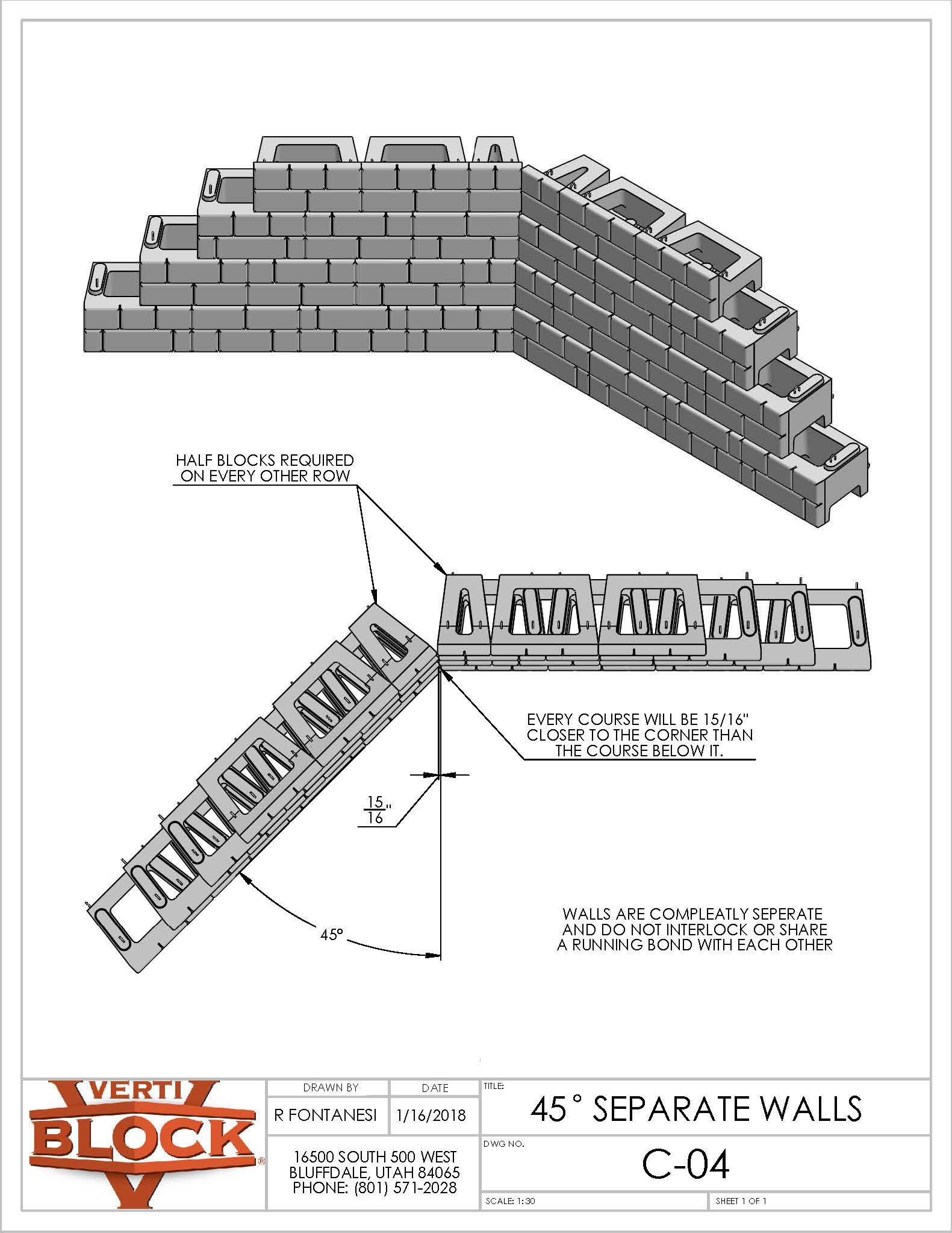
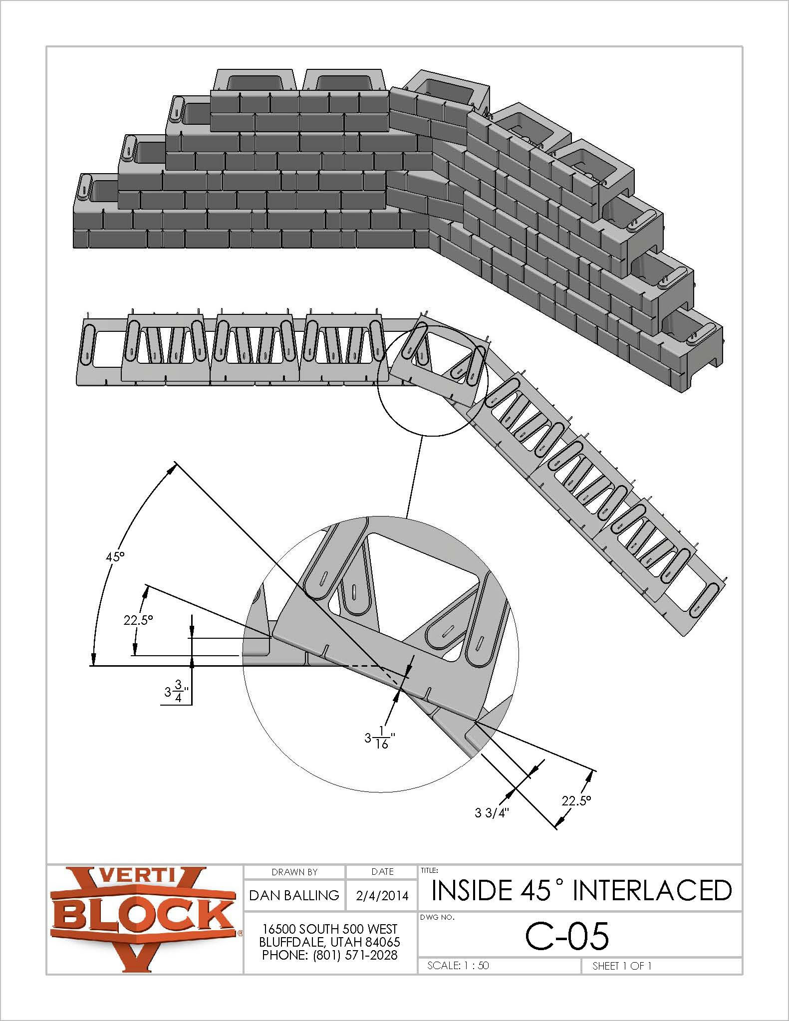
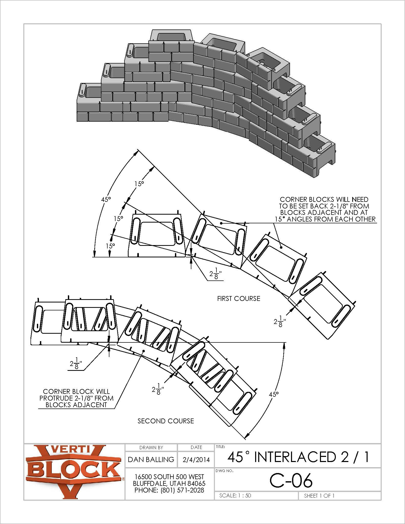
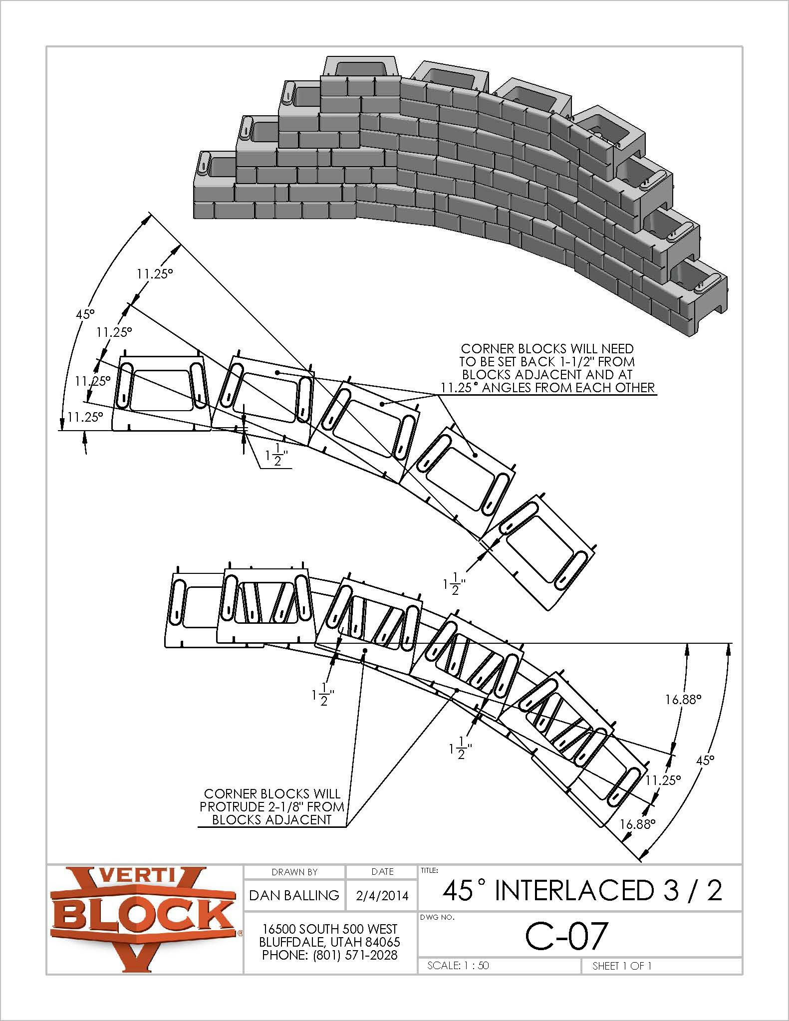
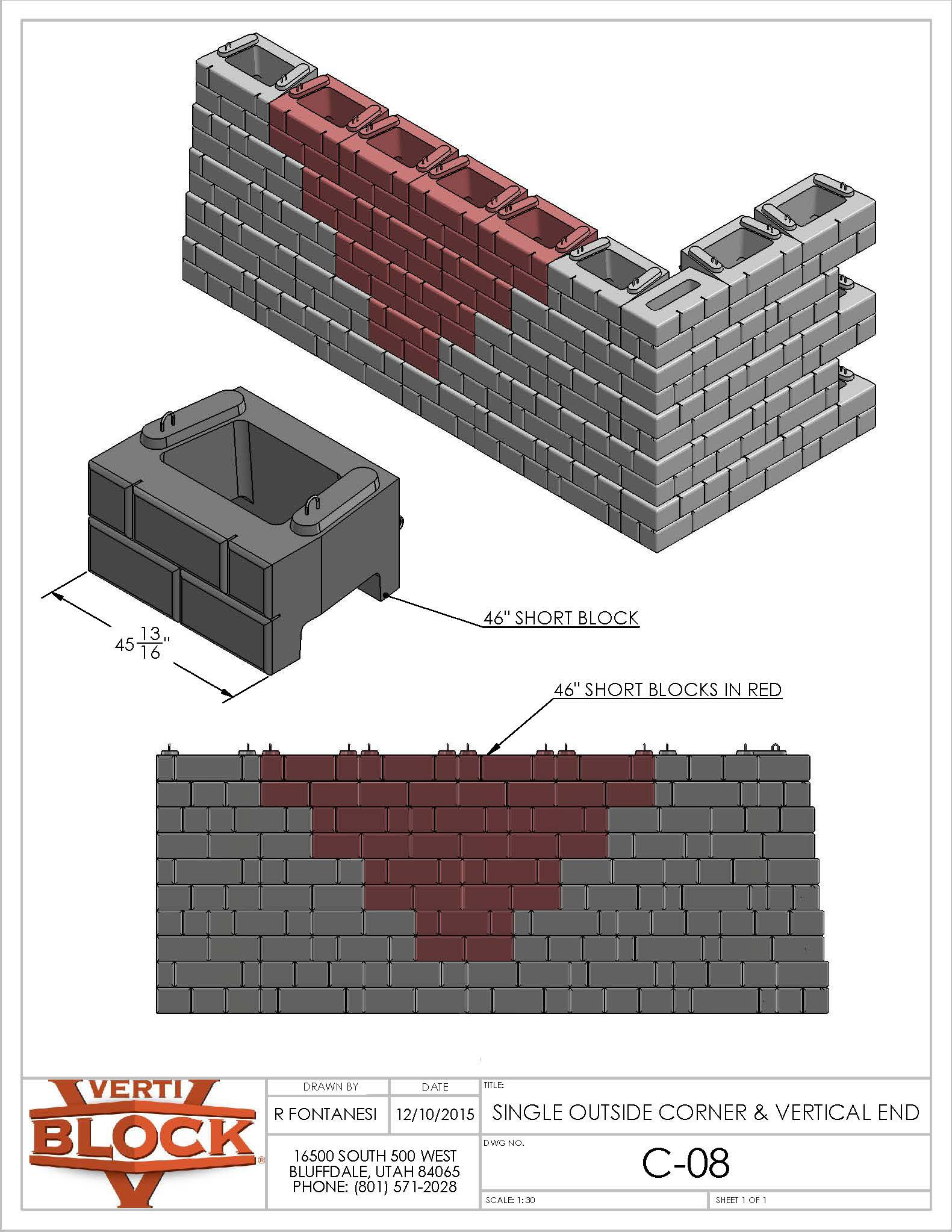
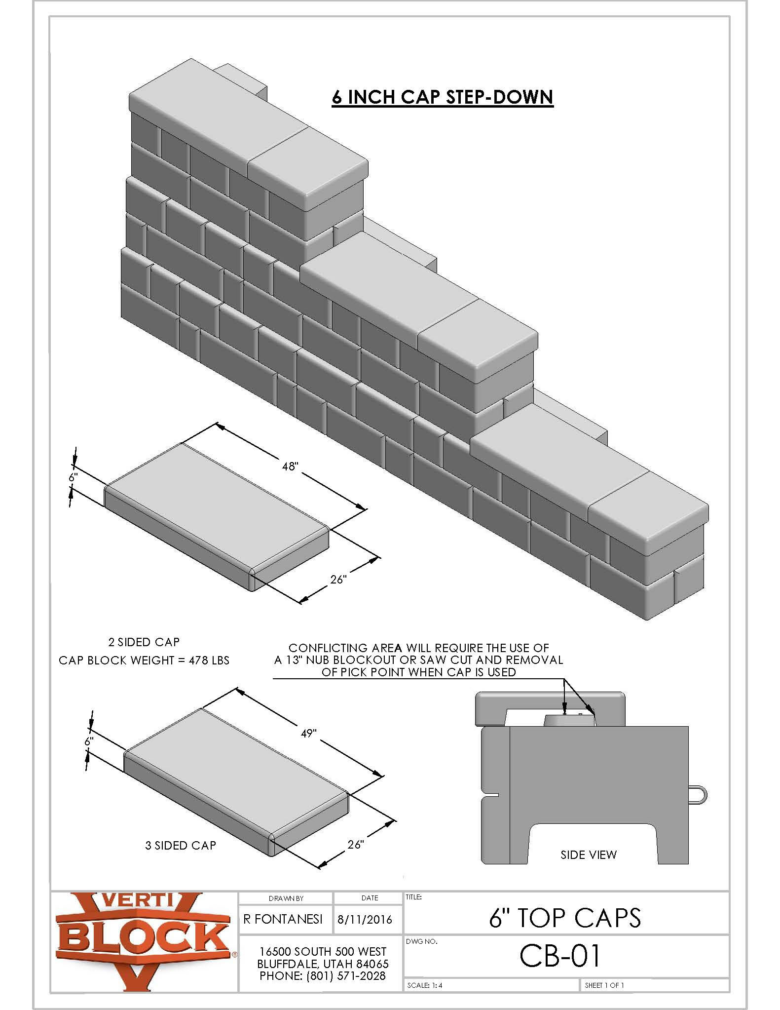
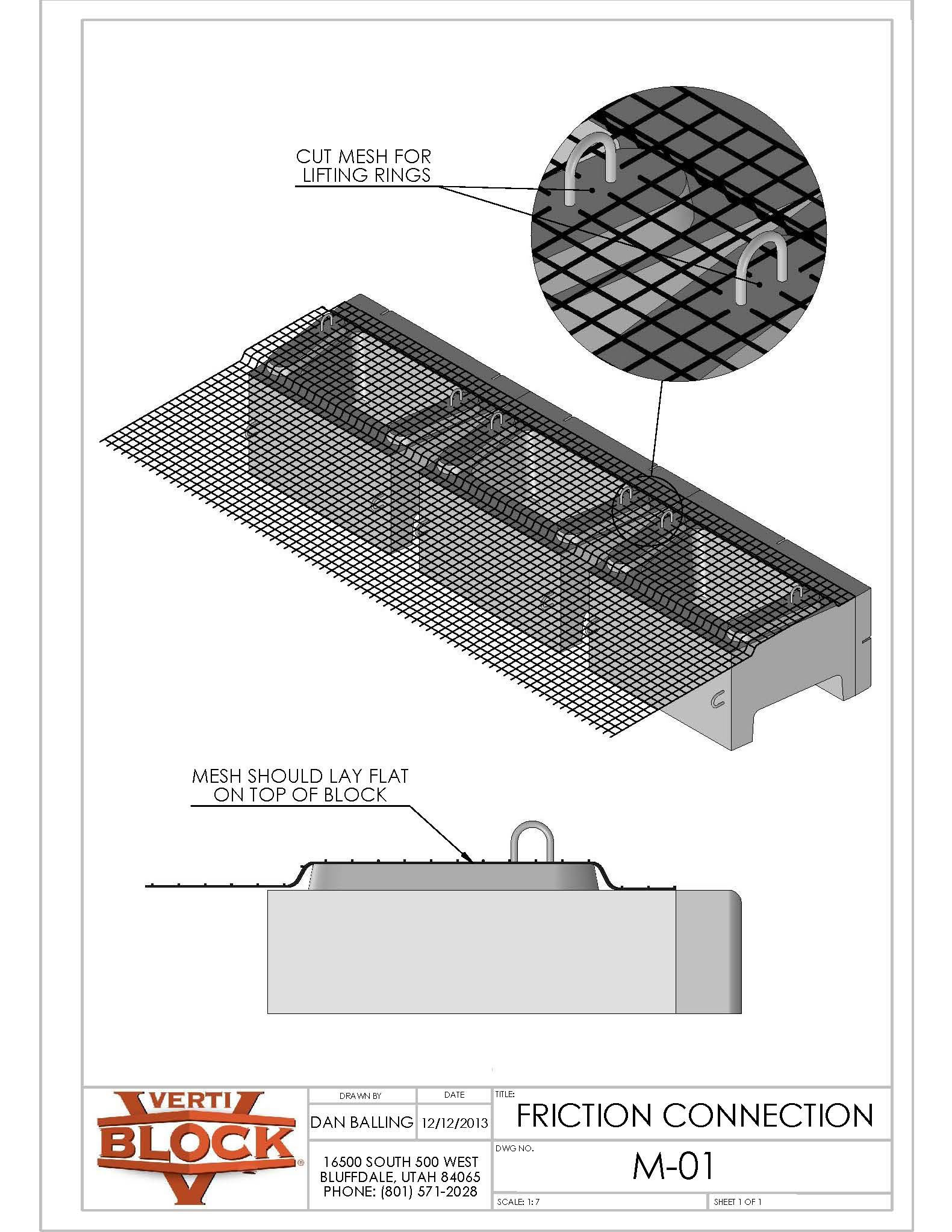
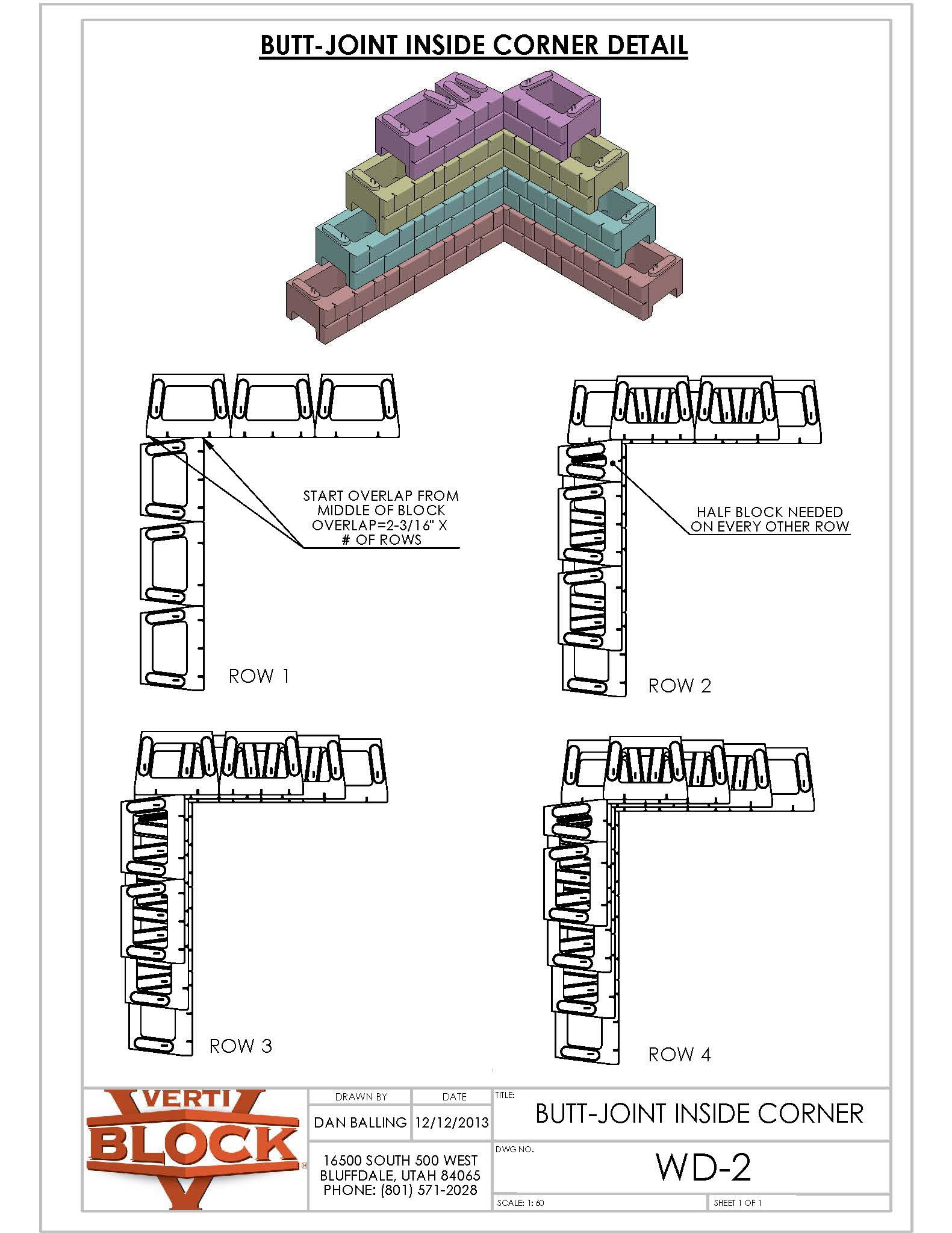
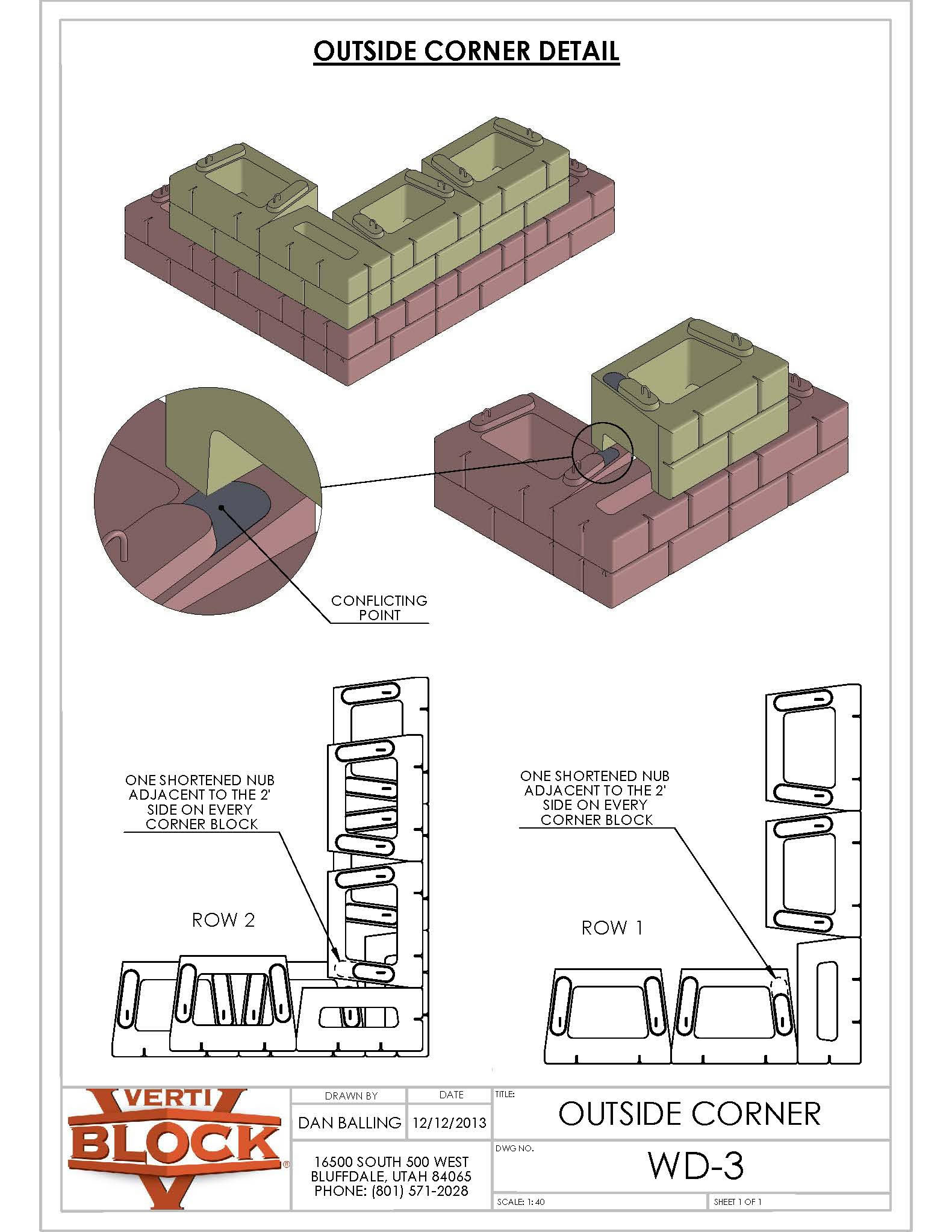
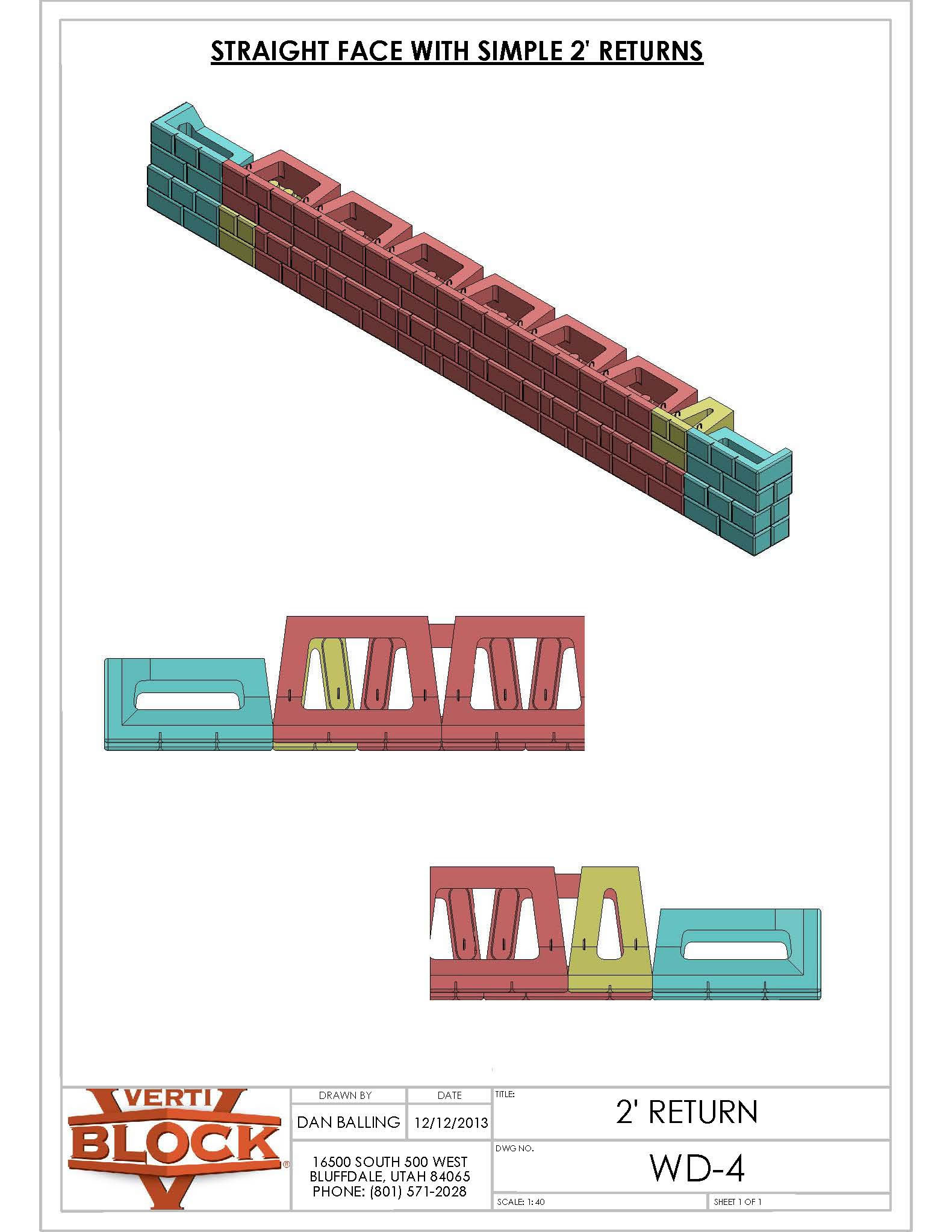
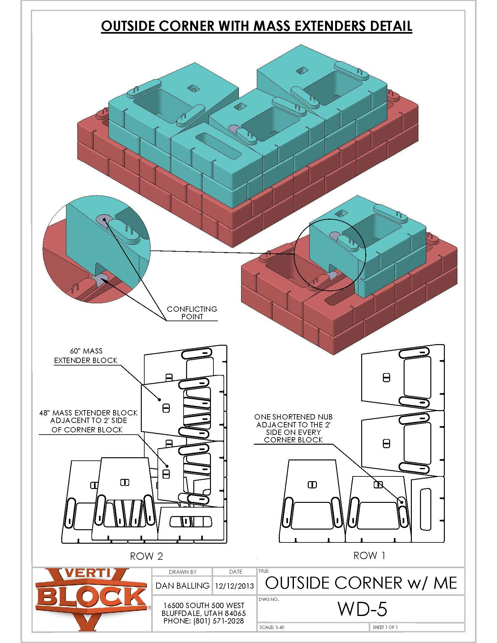
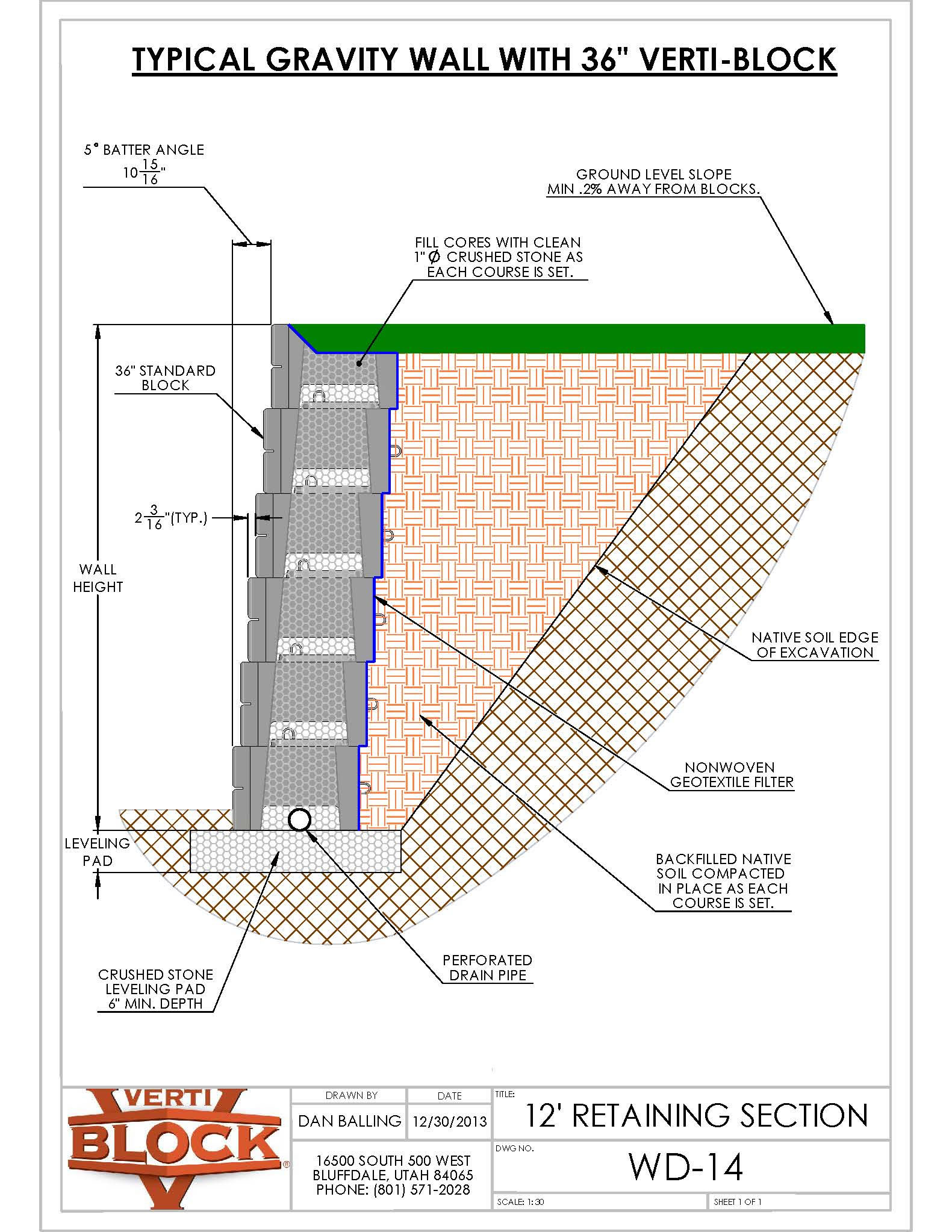
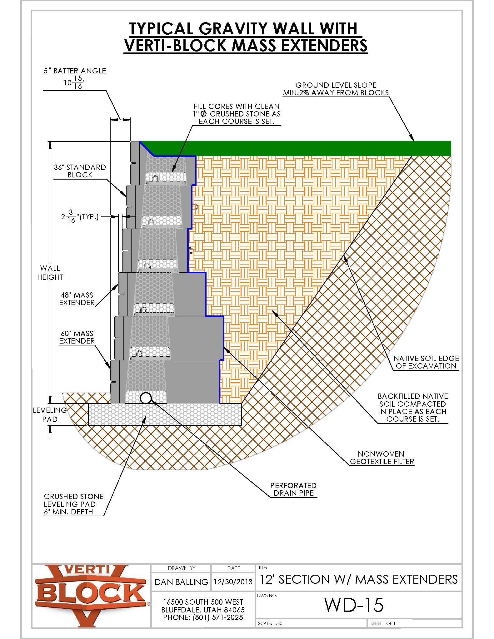
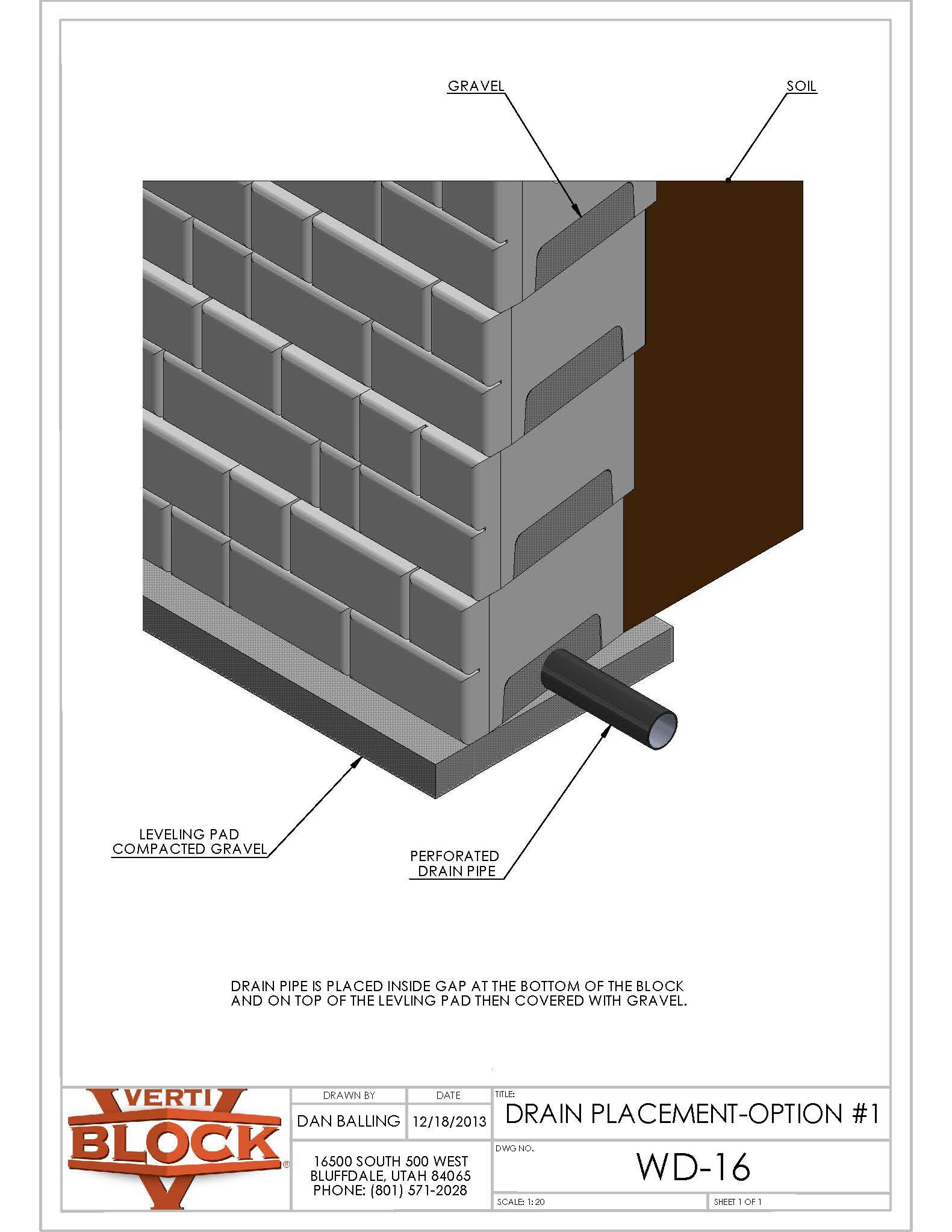
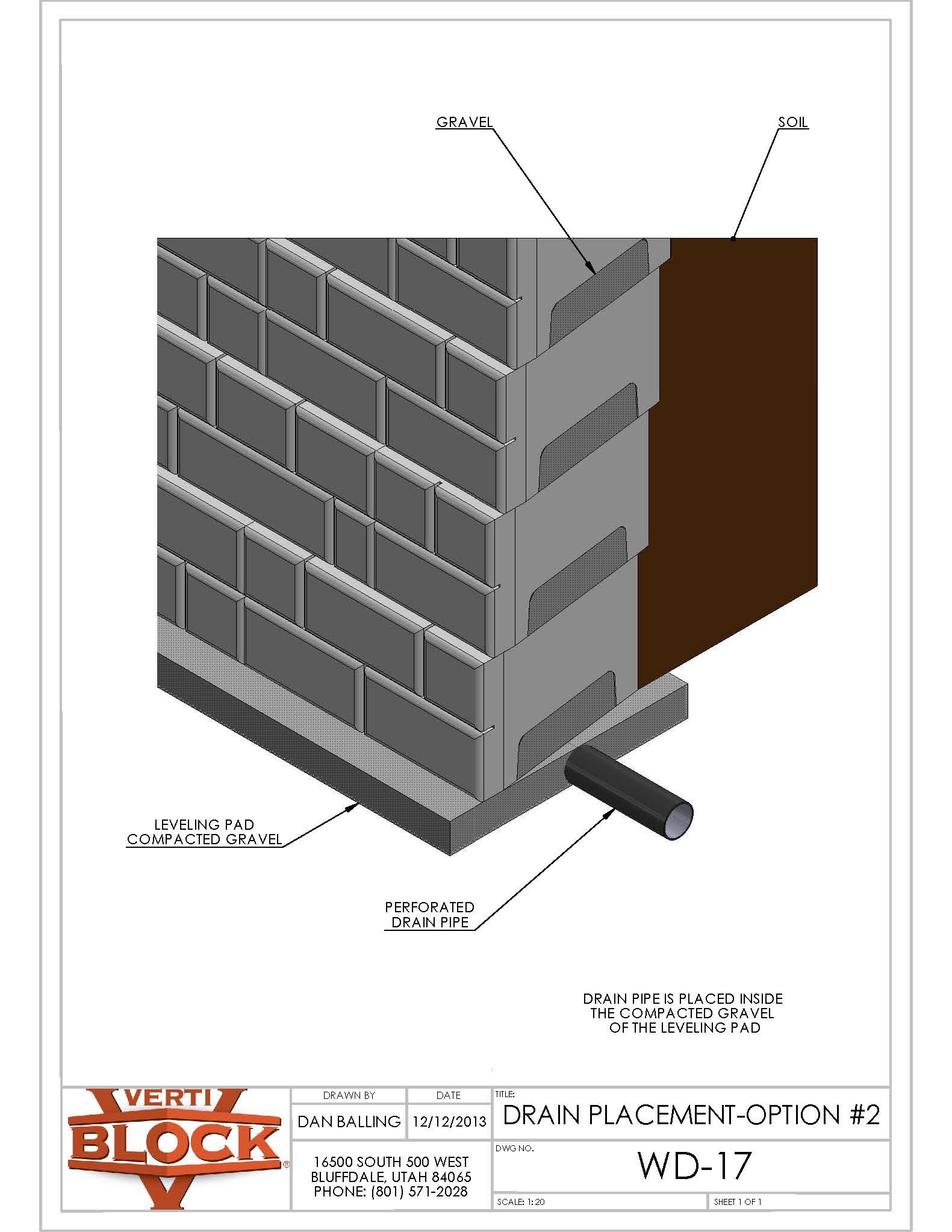
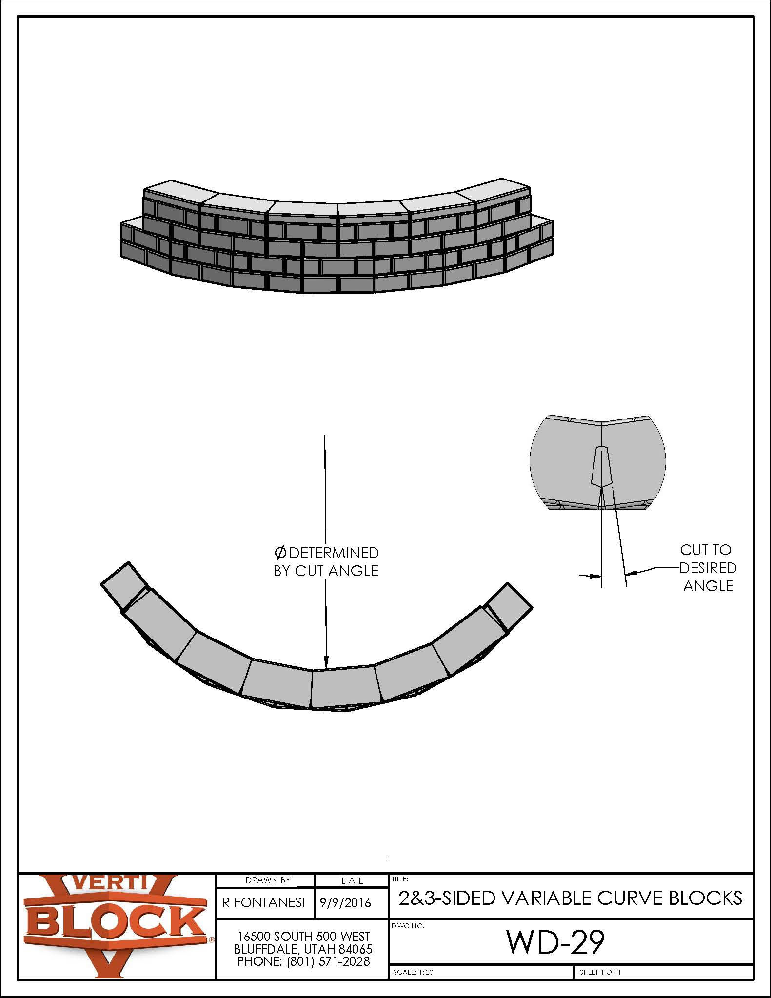
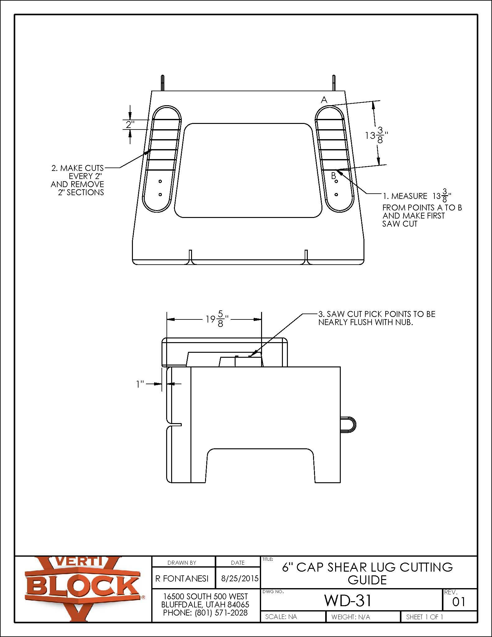
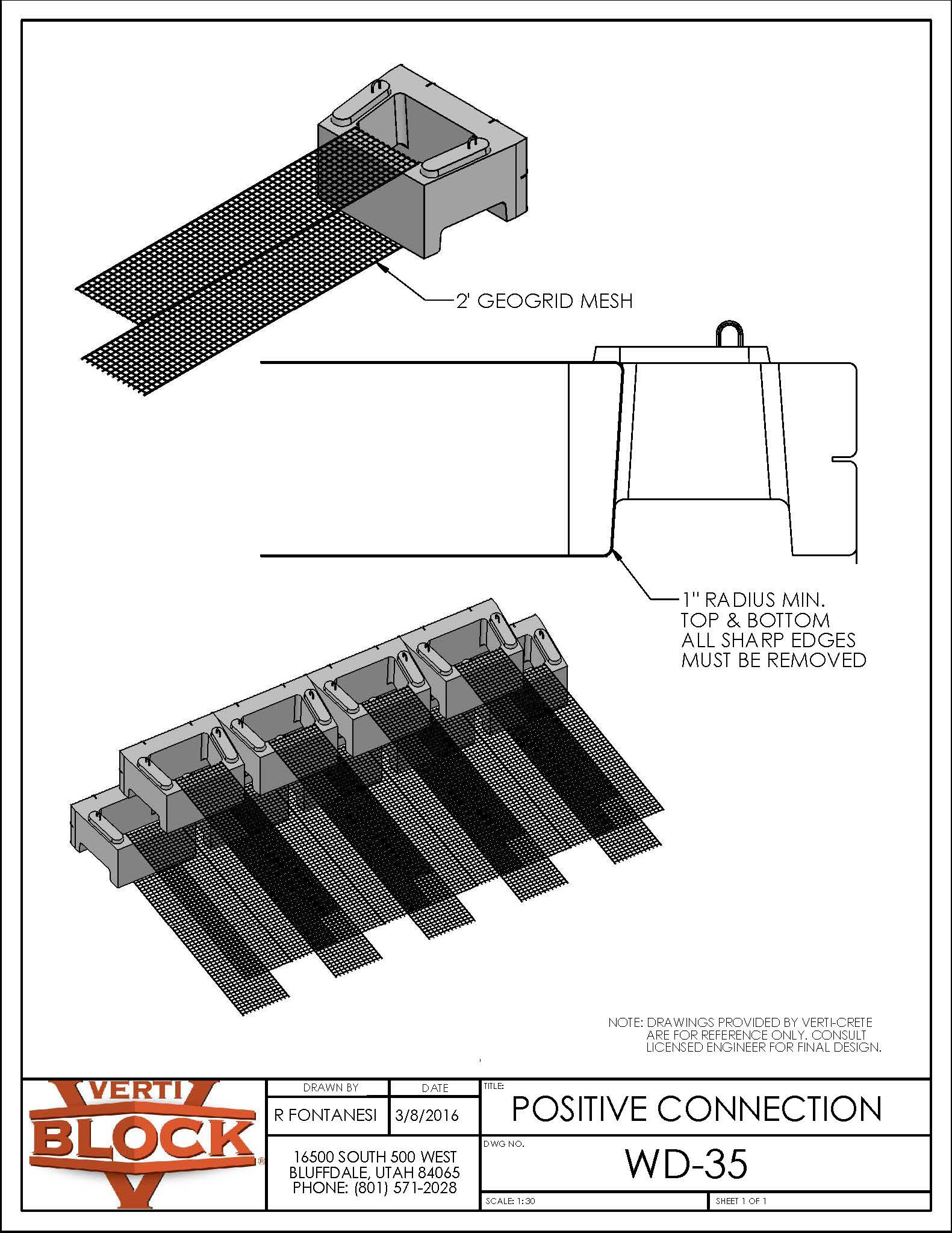
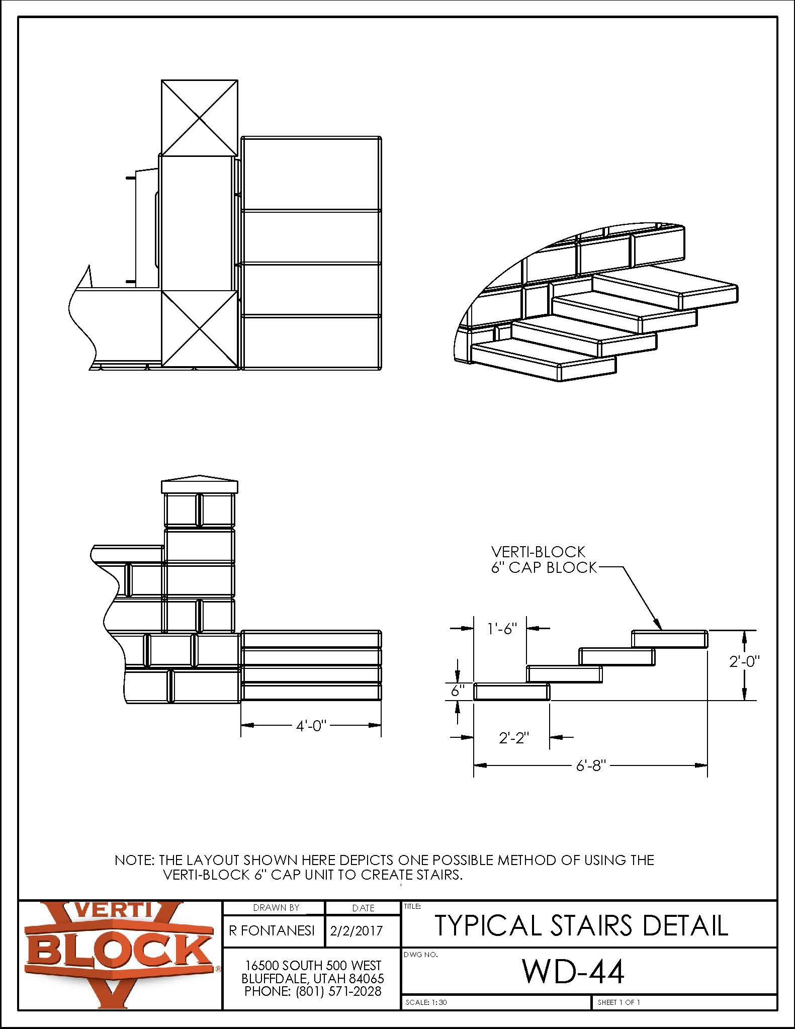
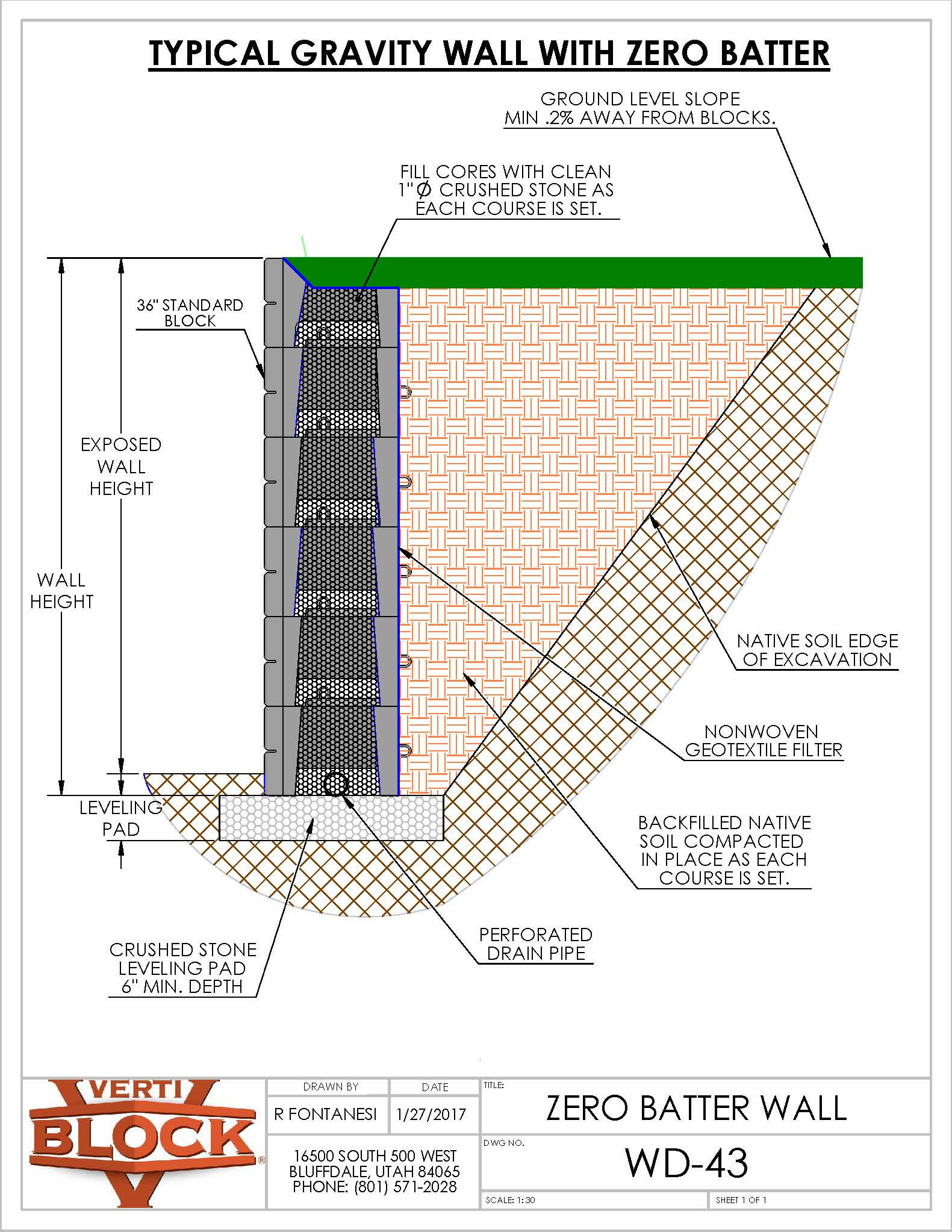
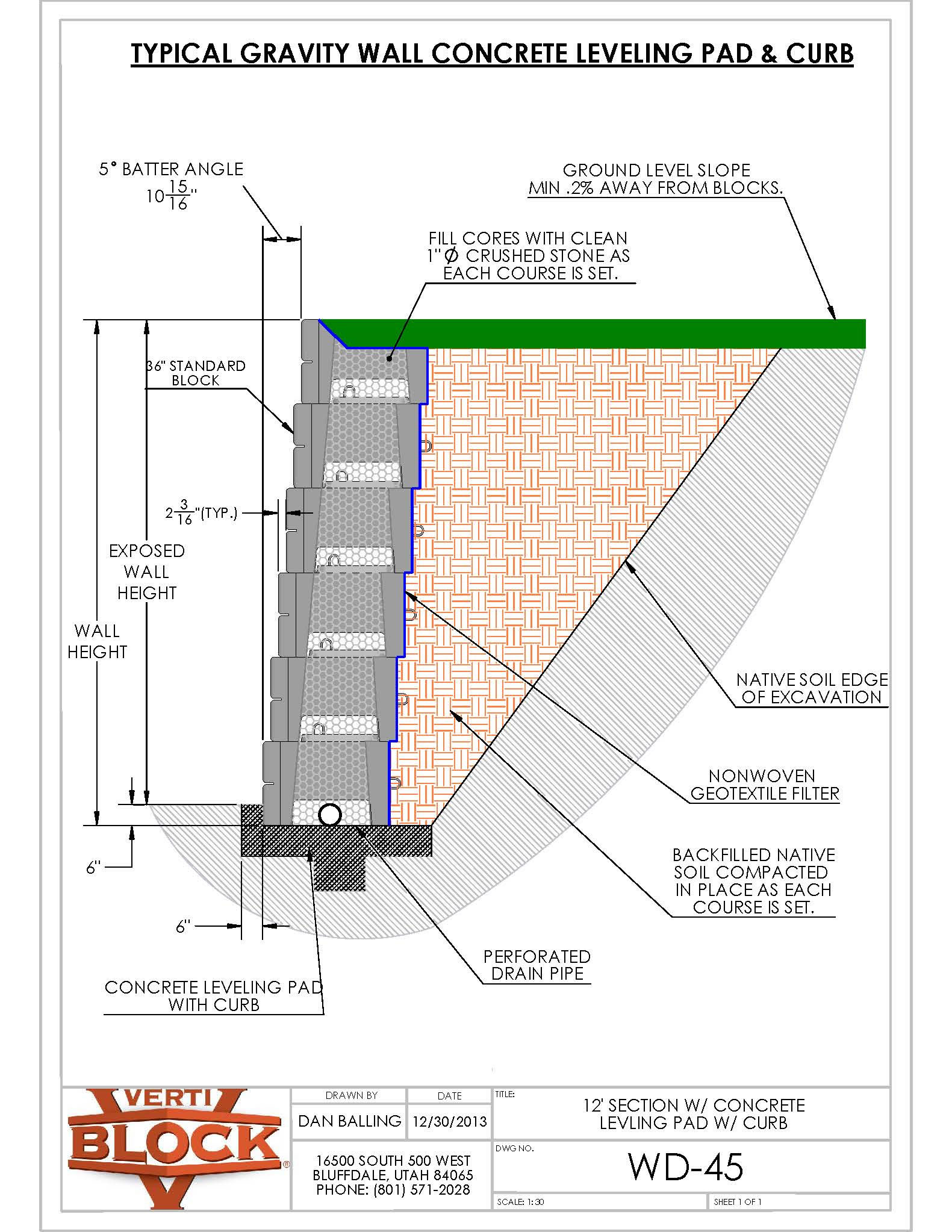
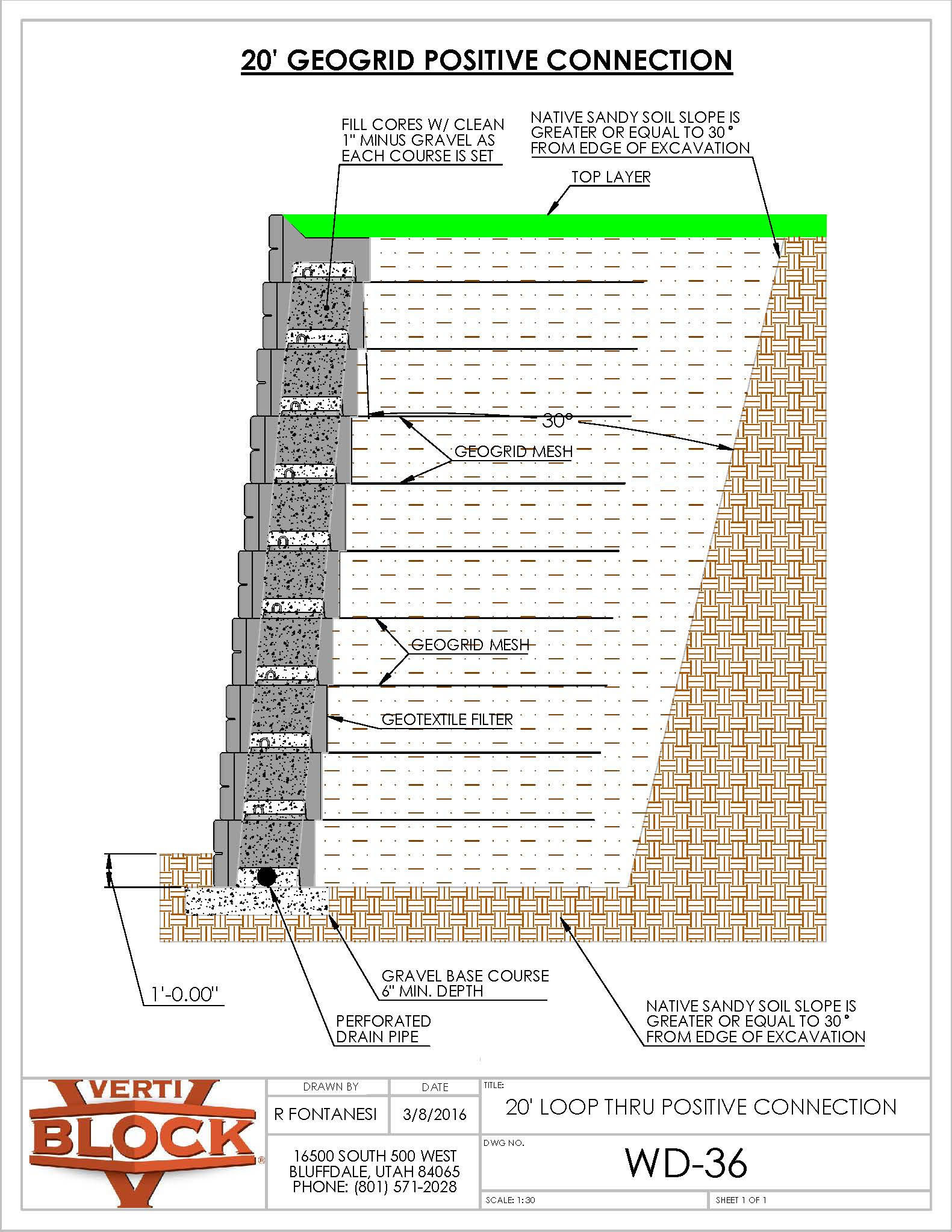
Block Details | Construction Drawings | Typical Wall Details

To download images only (not CAD) Left Click and click Save Image As

CAD Downloads

Technical drawing of the 36-inch block series showing six types of concrete blocks with dimensions and weights: Standard Block, Standard Top Block, Half Block, Half Top Block, Corner Block, and Corner Top Block.Technical drawing and data sheet of a 36-inch standard concrete block with gravel infill, showing dimensions, weight, volume, center of gravity, and a 3D block rendering.Technical drawing and 3D render of a 36-inch half concrete block with gravel infill, showing dimensions, center of gravity marks, and data tables for block weight, volume, and combined unit specifications.Technical drawing and data sheet for a 24-inch corner concrete block with gravel infill, showing dimensions, weight, volume, center of gravity, and a 3D block illustration.Technical drawing showing dimensions and weights of four mass extender blocks: 48-inch and 60-inch regular blocks, and 48-inch and 60-inch half blocks, with measurements in feet and block weights in pounds.Technical drawing and data sheet of 48-inch mass extender block showing front, side views, dimensions, concrete and gravel infill data, and company contact information.Technical drawing and data sheet for a 60 inch mass extender block with gravel infill, including dimensions, weight, volume, center of gravity, and a 3D block illustration.Technical drawing and 3D model of a 48-inch half block mass extender with dimensions, concrete block data, gravel infill data, combined unit data, and center of gravity measurements.Engineering drawing of a 60-inch half block mass extender with gravel infill, showing detailed dimensions, concrete block data, gravel infill data, combined unit data, and diagrams of block and gravel infill with center of gravity measurements.Engineering drawing of an 84-inch block mass extender with gravel infill, showing top, side, and isometric views with measurements and weight data.Engineering drawing showing side views and center of mass measurements for 48", 60", 72", and 84" mass extenders.Engineering drawing of a 72 inch mass extender block with gravel infill, including dimensions, center of gravity data, and a 3D block illustration.Technical drawing showing 2-sided and 3-sided block series with and without lugs, dimensions, and weights from VertiBlock.Technical drawing of six different half-step block designs with dimensions and weights, including standard, top, half, half top, corner, and corner top blocks, labeled with measurements in feet and inches and block weights in pounds.Technical drawing showing dimensions and mass info for two concrete gap inserts: Top Standard Gap Insert 22x10 inches, weight 102 lbs; Top Corner Gap Insert 19x10 inches, weight 62 lbs.Technical drawing and specifications of a 36-inch standard concrete block with gravel infill, showing dimensions, center of gravity, weights, and volume data, including isometric and side views.
Technical drawing showing a 45-degree outside corner of a VertiBlock wall system with instructions on block arrangement and running bond shifts.Technical drawing of a double 90-degree inside corner made with interlocking blocks, showing a 3D view and top view with label 'Alternate Overlapping Blocks.'Technical drawing of a double 90-degree outside corner constructed with interlocking concrete blocks, highlighting short blocks in red.Technical drawing showing 45-degree separate block walls with half blocks required every other row and no interlocking of walls.Technical drawing of interlaced concrete blocks forming a 45-degree inside corner with detailed measurements and angles.Technical drawing showing layout and angles for 45-degree interlaced Verti-Block corner blocks, with measurements and two course instructions.Technical drawing showing interlaced 45-degree corner VertiBlock layout with angles and setback measurements for block placement.Technical drawing of a single outside corner and vertical end concrete block wall using 46-inch short blocks highlighted in red, with measurements and Verti-Block logo.Technical drawing of a 6 inch cap step-down on a block wall, showing 2-sided and 3-sided cap dimensions and a side view with construction notes.Technical drawing showing mesh laid flat on a block with cutouts for lifting rings, labeled as Friction Connection by VertiBlock.Technical drawing of a planter row wall made of gray blocks with green soil on top, showing a side view with soil and leveling pad labels.Technical drawing showing isometric and back side views of a planter row outside corner block assembly.Technical drawing showing an inside corner of a planter row made of modular block pieces, with a note indicating batter increases by 2 3/16 inches per row.Technical drawing showing interlaced inside corner detail with colored 3D block illustration, three row diagrams, and close-up detail.Technical drawing showing butt-joint inside corner block assembly in four rows with overlap and half block instructions, featuring a colored 3D corner block model at the top.Technical drawing showing an outside corner block detail with 3D views of block placement, a zoomed-in conflicting point, and layout instructions for rows 1 and 2 with shortened nubs adjacent to the 2 foot side.Technical drawing showing a straight face concrete block wall with simple 2-foot returns, including 3D and side views with color-coded blocks.Technical illustration showing outside corner construction with mass extender blocks in two 3D views and detailed block placement diagrams for rows 1 and 2, highlighting conflicting points and block nubs.Technical drawing of a three-row outside curve wall with color-coded blocks and dimension details, labeled WD-06.Technical drawing showing a straight face wall with simple 4-foot returns made of colored blocks, including detailed block layout for three levels and assembly notes.Technical drawing showing a 2-foot step down with colored blocks and labeled top corner gap inserts for construction.Diagram showing a 6-foot step down construction with colored interlocking blocks and a labeled top standard gap insert component.Technical illustration showing assembly of a 6-foot step down with half-step block and top corner gap insert in multicolored blocks.Diagram showing assembly of 10-foot step down with half-step block and top standard gap insert, including labeled 3D block pieces in red, green, blue, and gray.Technical drawing showing color-coded inside curve detail with three rows of interlocking blocks in red, yellow, and blue, labeled with radii and a note on radius increments.Technical cross-section drawing of a sea wall detail showing concrete blocks with 1-inch minus gravel behind, non-woven geotextile fabric layers, and stone placement, annotated with construction notes and contact information.Technical diagram of a typical 12-foot gravity retaining wall with 36-inch Verti-Block showing block layers, crushed stone fill, perforated drain pipe, and soil layers.Technical diagram of a typical 12-foot gravity wall with Verti-Block mass extenders showing block dimensions, crushed stone fill, drain pipe, geotextile filter, and soil compaction details.Diagram showing drain placement option with a perforated drain pipe inside the gap at the bottom of a block wall, on a leveling pad of compacted gravel, covered by gravel and soil.Diagram showing drain placement option with perforated drain pipe inside compacted gravel leveling pad next to a block wall and soil.Diagram of block wall corner with labeled gravel backfill, soil, perforated drain pipe behind blocks, and compacted gravel leveling pad beneath.Technical drawing of a proposed river retaining wall detailing concrete blocks, geotextile liners, subbase, drainage, and steel sheet piling with construction measurements.Construction drawing of bridge abutments showing top, side, front, and isometric views with dimensions and Verti-Block logo.Engineering drawing showing an outside curve layout composed of multiple interlocking segments labeled WD-21 with radius measurement and a detailed joint close-up.Technical drawing illustrating an outside corner block assembly with 84-inch mass extenders, including labeled 72-inch, 48-inch, and 84-inch mass extender blocks and a zoomed view of a conflicting point.Technical drawing showing a half-step top row with one row of half-step blocks highlighted in red on a grey block structure.Technical drawing showing a wall section with one row of half step blocks highlighted in red in the second row.Technical drawing of a bottom row half-step block wall section showing grade level and a half-step block row segment.Technical diagram showing 2-sided and 3-sided concrete top caps with dimensions and wall block assembly for Verti-Block.Technical drawing showing 2- and 3-sided variable curve block configurations with cut angle instructions.Technical drawing of a 6-inch cap shear lug showing measurements and cutting instructions with labeled points A and B.Technical drawing of a Verti-Block Positive Connection WD-35 showing 2-inch geogrid mesh inserted through blocks with instructions for sharp edge removal.Technical drawing showing different views and dimensions of typical stairs made using Verti-Block 6-inch cap blocks.
Technical drawing showing cross-section of a sea wall with labeled layers including 1-inch minus gravel inside and behind blocks, non-woven geotextile fabric, stone on fabric, and notes for block depth and engineering specifications.Technical drawing of a typical 12-foot gravity retaining wall with 36-inch Verti-Block, showing block layers, crushed stone fill, perforated drain pipe, native soil, geotextile filter, and detailed measurements.Technical drawing of a typical 12-foot gravity retaining wall with Verti-Block mass extenders, showing layers, dimensions, and construction details including crushed stone leveling pad, perforated drain pipe, geotextile filter, and backfilled native soil.Technical cross-section diagram of a proposed river retaining wall with labeled components including concrete block wall, steel sheet piling, proposed railing, sidewalk, topsoil, geogrid, geotextile liner, drainable fill, and underdrain.Technical drawing of a 10-foot gravity retaining wall with 36-inch and 2-sided Verti-Block showing block cross-section, leveling pad, perforated drain pipe, backfilled native soil, and construction details.Technical drawing of a gravity wall with fence showing labeled components like fence height, wall height, leveling pad, crushed stone leveling pad, perforated drain pipe, non-woven geotextile fiber, and slope details.Technical drawing of a typical 12-foot gravity retaining wall with 12-inch setback showing block layers, soil layers, drainage pipe, and construction details.Technical cross-section drawing of a lakeshore wall detailing layers including native soil, backfilled soil, perforated drain pipe, and leveling pad.Technical drawing of a typical gravity wall with zero batter, showing blocks filled with crushed stone, backfilled compacted soil, perforated drain pipe, and nonwoven geotextile filter.Technical drawing showing a typical gravity wall with concrete leveling pad and curb, including dimensions, materials, and cross-section details.Technical drawing of a 20-foot geogrid positive connection showing layers of native sandy soil, geogrid mesh, geotextile filter, gravel base course, and perforated drain pipe beside a retaining wall.
Technical diagram showing six types of 36-inch concrete blocks with dimensions and weights, including standard, standard top, half, half top, corner, and corner top blocks.Engineering diagram of a 36-inch standard concrete block with gravel infill, showing top and side views with measurements, shaded gravel infill areas, and data tables for block and gravel weights, volumes, and center of gravity values.Technical drawing and data sheet for a 36-inch half concrete block with gravel infill, including block dimensions, weight, volume, center of gravity, and combined unit data.Technical drawing and data sheet for a 24-inch corner concrete block with gravel infill, including dimensions, weight, volume, center of gravity, and a 3D block illustration.Diagram of VertiBlock Mass Extender Block Series showing 48-inch and 60-inch regular and half block models with dimensions and weights.Technical drawing and data sheet for a 48-inch mass extender block with gravel infill, showing dimensions, concrete block and gravel infill weight and volume details, and center of gravity measurements.Technical drawing and data sheet for a 60-inch mass extender block with gravel infill, showing front, side, and 3D views, dimensions, center of gravity measurements, and weight specifications.Technical drawing and data sheet for a 48-inch half block mass extender with front, side, and top views, including weight, volume, and center of gravity metrics.Technical drawing and data sheet of a 60-inch half block mass extender with gravel infill showing 3D view, dimensions, concrete block data, gravel infill data, combined unit data, and company contact information.Technical drawing showing dimensions, weight, and center of gravity data for an 84-inch block mass extender with gravel infill, including block and infill details and company logo.Technical drawing showing side views and center of mass measurements for 48, 60, 72, and 84 inch VertiBlock mass extenders.Technical drawing and data sheet of a 72-inch Mass Extender Block with gravel infill, showing dimensions, concrete and gravel data, combined unit weight, and center of gravity measurements.Technical drawings of four concrete blocks in the 2 & 3 sided block series, showing dimensions and weights for blocks with and without lugs.Technical drawing of Verti-Block half-step block series showing six block types with dimensions and weights.Technical drawing of two gap inserts with dimensions and mass info, labeled Top Standard Gap Insert and Top Corner Gap Insert, including measurements in inches and weight in pounds.Technical drawing of a 36-inch standard concrete block with gravel infill, showing dimensions, weight, center of gravity, and volume data.Technical drawing illustrating a 45-degree outside corner wall using VertiBlock concrete blocks, showing block layout with 20.5 inch setback, 45-degree angle, and running bond shifts of 3/4 inch per row.Technical drawing of a double 90-degree inside corner made with overlapping masonry blocks, showing 3D and top views.Technical drawing of a double 90 degree outside corner block wall with short blocks highlighted in red and dimensions for a short block.Technical drawing showing 45-degree separate walls built with concrete blocks, with notes on half block usage and spacing.Technical drawing showing the inside 45-degree interlaced construction of Verti-Block with detailed angle and measurement annotations.Technical drawing showing 45-degree interlaced corner block arrangement with measurements and two courses.Technical drawing showing interlaced Verti-Block corner blocks set at 45-degree angles with detailed measurements and spacing instructions.Technical drawing showing a single outside corner and vertical end block wall with highlighted red 46-inch short blocks and a detailed 3D block model with dimensions.Technical drawing of a 6-inch cap step-down wall with dimensions and side view, including 2-sided and 3-sided cap block measurements.Technical drawing showing mesh placement over a VertiBlock with cutouts for lifting rings and a side view emphasizing the mesh lay flat on top of the block.Isometric drawing of a planter row wall made of gray interlocking blocks with soil on top and a cross-section showing soil and leveling pad.Technical drawing showing a three-dimensional corner assembly of interlocking concrete planter blocks with two back side views and details for assembly.Technical drawing of a VertiBlock planter row inside corner showing staggered block arrangement with batter increasing by 2 3/16 inches per row.Technical drawing illustrating the interlaced inside corner detail of VertiBlock construction blocks, showing three different block rows and an enlarged detail of corner overlap.Technical drawing showing a butt-joint inside corner detail for concrete blocks in four rows with instructions on block overlap and half blocks needed.Technical drawing showing an outside corner detail of VertiBlock construction blocks with diagrams of block placement and a highlighted conflicting point.Technical drawing showing a straight concrete block wall with simple 2-foot returns in three different views with color-coded blocks, titled '2' Return' DWG WD-4 by Dan Balling.Technical drawing showing assembly detail of outside corner blocks with mass extenders, including 3D renderings and labeled component sections.Technical drawing illustrating the outside curve detailing of block rows in blue, green, and red with radius and setback measurements.Technical drawing showing a masonry wall with simple 4-foot returns, including corner block arrangements for three levels and instructions for block positioning.Diagram showing a 2-foot step down construction with top corner gap inserts in red, green, and blue interlocking blocks, including a close-up of the top corner gap insert piece.Technical drawing showing a 6-foot step down design with colored block sections and a labeled top standard gap insert.Technical drawing of a 6-foot step down with half-step corner block and top corner gap insert in colored block illustrations.Diagram showing a 10-foot step down with half-step block and top standard gap insert components in different colors.Technical drawing showing the inside curve detail for Verti-Block, depicting three rows of colored blocks in red, yellow, and blue with increasing radii and notes on radius setbacks.Technical drawing illustrating sea wall detail WD-13 with labeled components including gravel inside and behind block, non-woven geotextile fabric, stone placement, and block depth specifications.Technical drawing of a typical gravity retaining wall using 36-inch Verti-Block with labeled components including crushed stone leveling pad, perforated drain pipe, geotextile filter, backfilled compacted native soil, and batter angle details.Technical drawing of a typical gravity wall with verti-block mass extenders showing block dimensions, fill materials, drain pipe, soil backfill, and leveling pad.3D diagram showing drain placement with perforated drain pipe inside block gap, on leveling pad of compacted gravel, covered by gravel and soil.Diagram showing drain placement option with perforated drain pipe inside compacted gravel leveling pad beside a block wall, with soil and gravel layers indicated.3D diagram showing a block wall with a perforated drain pipe placed behind the blocks on top of a leveling pad of compacted gravel, with soil and gravel layers labeled.Detailed technical cross-section drawing of a proposed retaining wall with labeled construction elements including concrete block wall, proposed railing, sidewalk, topsoil, subbase, geogrid, geotextile liner, drainable fill, steel sheet piling, and underdrain.Construction drawing of Verti-Block curved bridge abutments showing front, side, top, and angled views with dimensions.Technical drawing of Verti-Block outside curve with 84-inch ME, showing segmented curved blocks and detail of spacing with radius measurement.Technical drawing and colored 3D illustration showing the outside corner assembly with mass extenders on interlocking blocks, highlighting conflicting points and extender block dimensions for construction.Technical drawing showing a half step top row with one row of half step blocks highlighted in red, along with the Verti-Block logo and drawing details.Technical drawing of a half step 2nd row concrete block wall with one row of half step blocks highlighted in red.Technical drawing showing a bottom row half-step block wall segment with labels for grade and half-step block row segment.Technical drawing of a gravity retaining wall with 36-inch and 2-sided Verti-Block, showing exposed wall heights, crushed stone leveling pad, perforated drain pipe, geotextile filter, and soil backfill details.Technical drawing showing 2-sided and 3-sided concrete blocks with top caps, including dimensions and assembly details.Technical drawing of 2- and 3-sided variable curve blocks with cut angle instructions and contact information for Verti-Block.Technical drawing of a 6-inch cap shear lug with measurements and cutting instructions, including a top view and side view.Technical drawing of a gravity wall with fence showing labeled components including fence height, wall height, leveling pad, crushed stone pad, perforated drain pipe, non-woven geotextile fiber, native soil, and ground slope.Technical drawing of a 12-foot gravity retaining wall with 12-inch setback showing block sizes, batter angle, leveling pad, drainage pipe, and soil details.Technical drawing showing Verti-Block positive connection with 2-foot geogrid mesh integrated, featuring multiple blocks lined up with mesh extending from each.Technical diagram illustrating a 20-foot geogrid positive connection with labeled layers including geogrid mesh, gravel base course, perforated drain pipe, and native sandy soil slope at 30 degrees.Technical cross-section diagram of a lakeshore retaining wall labeled WD-42 showing wall height, lake depth, embedment, backfilled native soil, native soil edge of excavation, and a perforated drain pipe.Technical drawing of a typical gravity wall with zero batter showing block layout, crushed stone fill, perforated drain pipe, leveling pad, native soil excavation, geotextile filter, and backfilled compacted soil.Technical drawing showing typical stairs detail with dimensions and Verti-Block 6 inch cap blocks.Technical drawing of a typical gravity wall with concrete leveling pad and curb, showing block dimensions, ground slope, soil layers, and drainage pipe details.